Inst ToolsInst ToolsInst Tools
  • Courses
  • Automation
    • PLC
    • Control System
    • Safety System
    • Communication
    • Fire & Gas System
  • Instrumentation
    • Design
    • Pressure
    • Temperature
    • Flow
    • Level
    • Vibration
    • Analyzer
    • Control Valve
    • Switch
    • Calibration
    • Erection & Commissioning
  • Interview
    • Instrumentation
    • Electrical
    • Electronics
    • Practical
  • Q&A
    • Instrumentation
    • Control System
    • Electrical
    • Electronics
    • Analog Electronics
    • Digital Electronics
    • Power Electronics
    • Microprocessor
  • Request
Search
  • Books
  • Software
  • Projects
  • Process
  • Tools
  • Basics
  • Formula
  • Power Plant
  • Root Cause Analysis
  • Electrical Basics
  • Animation
  • Standards
  • 4-20 mA Course
  • Siemens PLC Course
Reading: Introduction to Chemical Dosing System
Share
Notification Show More
Font ResizerAa
Inst ToolsInst Tools
Font ResizerAa
  • Courses
  • Design
  • PLC
  • Interview
  • Control System
Search
  • Courses
  • Automation
    • PLC
    • Control System
    • Safety System
    • Communication
    • Fire & Gas System
  • Instrumentation
    • Design
    • Pressure
    • Temperature
    • Flow
    • Level
    • Vibration
    • Analyzer
    • Control Valve
    • Switch
    • Calibration
    • Erection & Commissioning
  • Interview
    • Instrumentation
    • Electrical
    • Electronics
    • Practical
  • Q&A
    • Instrumentation
    • Control System
    • Electrical
    • Electronics
    • Analog Electronics
    • Digital Electronics
    • Power Electronics
    • Microprocessor
  • Request
Follow US
All rights reserved. Reproduction in whole or in part without written permission is prohibited.
Inst Tools > Blog > Common > Introduction to Chemical Dosing System

Introduction to Chemical Dosing System

The chemical dosing system mainly consists of a storage container, dosing pumps, level instruments, switches, and valves.

Last updated: May 7, 2021 4:23 pm
Editorial Staff
Common Process
1 Comment
Share
5 Min Read
SHARE

Chemical dosing is one of the most crucial processes in Wastewater Treatment. The main motto behind chemical dosing is Phosphate Removal & pH maintenance.

Contents
Process OverviewProcess DiagramProcess StepsManual ModeAuto ModeConclusion

Due to various chemical reactions & processes followed in industries, there are high chances of increasing the pH of used water. If such water is discharged into the rivers, lakes, etc., there are high chances of threat to Human Life & Bio life as well.

The environmental regulating bodies prescribe the exact quality of water to be discharged into main streams.

The major chemicals used in wastewater treatment are

  • pH neutralizers (Sodium Hydroxide / Caustic)
  • Coagulants
  • Flocculants

Process Overview

The chemical dosing system mainly consists of a storage container, dosing pumps, level instruments, switches, and valves. The location of dosing is mainly decided by chemical engineers or process engineers.

The container is equipped with level indicators so that it can be filled efficiently by observing the volume of chemical used.

The dosing pumps fetched the required chemical from container with the help of actuators.

The valves at the outlet of dosing pumps are On/Off valves to regulate the flow of chemicals at the location.
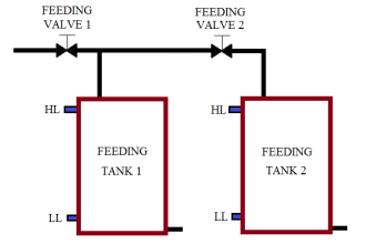
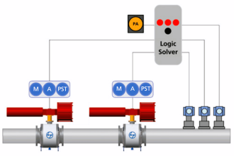
Process Diagram

Chemical Dosing Control System

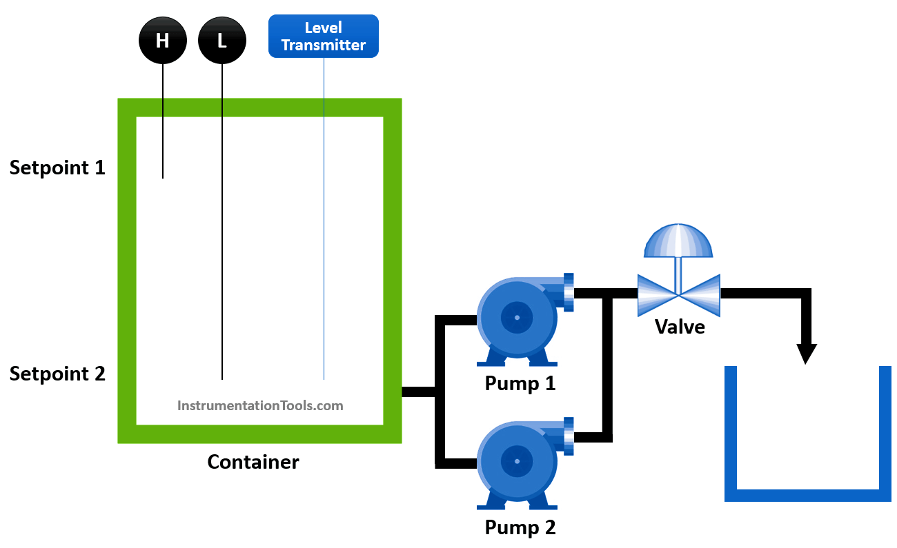
 The above typical dosing unit consists of a chemical container with Level Instruments & Switches. It shall indicate the chemical contained in the container.

The dosing pumps 1 & 2 shall operate in Duty / Standby mode in order to maintain the redundancy. The outlet valve shall discharge the chemical into the point of location.

Process Steps

The operator has the facility to dose the chemical in Auto / Manual Modes from HMI / SCADA.

Manual Mode

In manual mode, the operator shall manually observe the level in the container using the level instrument and probes displayed on HMI / SCADA.

If there is sufficient level in the container the operator shall manually open the valve and then enter the start command to Dosing Pump 1 or 2 and enter the required dosing rate (SP1) at HMI / SCADA.

The dosing pump shall continue to dose chemical at operator settable dose rate (l/h).

Once the sufficient dosing is done, operator shall manually stop the dosing pump and close the valve.

Auto Mode

In Auto mode, PLC / DCS shall take care of the steps followed by the operator in manual mode.

The sequence of steps shall be as follows

  • The operator enables the dosing process from HMI / SCADA.
  • The level in the container goes above the operator settable dosing start level (SP1).
  • The open command shall be sent to Valve.
  • Once the valve open feedback is received, the dosing pump 1 or 2 start command shall be sent along with operator adjustable dose rate (l/h).
  • The dosing shall continue until level in container falls below operator settable dosing stop level (SP2).
  • The low level switch shall be interlocked to dosing pump 1 & 2 to avoid dry running.
  • The valve open feedback shall be interlocked to dosing pump 1 & 2 to avoid pipeline burst.

Container Filling Operation

  • The filling operation is normally done under the observation of the plant operator.
  • The operator shall observe the level in the container using the level instrument.
  • If there is an insufficient chemical in the tank, then the operator shall ask to fill the tank until a sufficient level is reached.
  • The high-level switch is used to avoid overfilling of the container.

Conclusion

Here we observed a typical dosing process where the instrumentation engineer along with the chemical engineer applied the design & development concepts to automate the dosing system.

The safety of the plant is taken care of by the instrumentation engineer by applying the safety interlocking the dosing pumps and filling operation.

Author: NMG

If you liked this article, then please subscribe to our YouTube Channel for Instrumentation, Electrical, PLC, and SCADA video tutorials.

You can also follow us on Facebook and Twitter to receive daily updates.

Read Next:

  • Hydrazine Analyzer Working Principle
  • Temperature & Pressure on Level Measurement
  • Strain Gauge Pressure Sensor Principle
  • Breather Valve Working Principle
  • Chemical Sensors Objective Questions
Don't Miss Our Updates
Be the first to get exclusive content straight to your email.
We promise not to spam you. You can unsubscribe at any time.
Invalid email address
You've successfully subscribed !

Continue Reading

What is a Router? How Does a Router Work?
Water Treatment Plant
How Not to Install an Instrument and Wrong Practices
Bellows Steam Trap
Heat Exchanger Root Cause Analysis (RCA)
General Streams in Electronics Engineering for Students
Share This Article
Facebook Whatsapp Whatsapp LinkedIn Copy Link
Share
1 Comment
  • Martin says:
    May 9, 2021 at 6:57 am

    Thank you. Pl add details about plant interlocks.

    Reply

Leave a Reply Cancel reply

Your email address will not be published. Required fields are marked *

Stay Connected

128.3kFollowersLike
69.1kFollowersFollow
210kSubscribersSubscribe
38kFollowersFollow

Categories

Explore More

Various Types of Engineering Courses
Heat Transfer Loops in HVAC System
HVAC Double Effect Absorption Chiller
Difference Between NPT, BSPP and BSPT Seals
Recommendations to HVAC Engineers
How Technology is Shaping the Future of Education?
Field Instrumentation Tips
Modern Engineering Solutions for Rotary Equipment

Keep Learning

Load Cell Assembly

Urea Bagging Plant – Process Flow

Multiplexing

Introduction to Digital Systems

Circuit Diagram of Displacement Transducer

What is a Displacement Transducer? – Types and Advantages

What is Pump Redundancy

What is Pump Redundancy?

Various Codes used in CNC Programming

Various Codes used in CNC Programming

RJ45 Connector Pins

How to make RJ45 cable

Shaper Machine Hydraulic Circuit Design

Hydraulic Shaper Machine – Components, Circuit, Principle

Home Heating

What Type of Heating is Best for Your Home?

Learn More

Zener Barrier Protection

Zener Diode Barrier Principle

Multiple Thermowell Installations Problems

Multiple Thermowell Installations Problems

Online time of the PLC

System and Local Time in PLC

Photo Electric Transducers Objective Questions

Photo Electric Transducers Objective Questions

hard disk drive

Difference Between HDD and SSD

Networking Interview Questions

Top 100 Networking Interview Questions & Answers

Capacitance-Level-Transmitter

Capacitance Level Switch Calibration

Voltage Control & Circuit Breakers Interview Questions

Voltage Control & Circuit Breakers Interview Questions

Menu

  • About
  • Privacy Policy
  • Copyright

Quick Links

  • Learn PLC
  • Helping Hand
  • Part Time Job

YouTube Subscribe

Follow US
All rights reserved. Reproduction in whole or in part without written permission is prohibited.
Welcome Back!

Sign in to your account

Username or Email Address
Password

Lost your password?