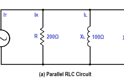
A 30 Ω resistance and a 40 Ω XC are in parallel with a 120V power source, as shown in Figure.
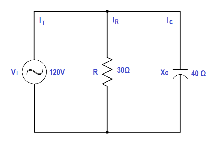
Figure : Parallel R-C Circuit
Find:
- Current, IT
- Z
- Power Factor, pf
- True Power, P
- Reactive Power, Q
- Apparent Power, S
Solution:
1.Current, IT
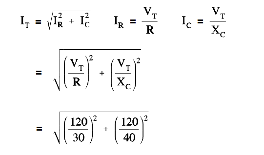
IT = 5 amps
2. Calculate Z
Z = VT/IT
Z = 120/5
Z = 24 Ω
3. Calculate Power factor (pf)
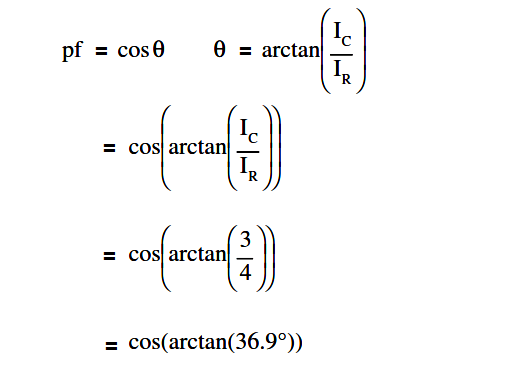
p.f. = 0.8
4. Calculate True Power, P
P = EI cos θ
P = (120)(5)(0.8)
P = 480 watts
5. Calculate Reactive Power, Q
Q = EI sin θ
Q = (120)(5)(0.6)
Q = 360 VAR
6. Calculate Apparent Power, S
S = EI
S = (120)(5)
S = 600 VA