A system which finds more interest in new PLC programmers is a burglar alarm system. Because alarms are a critical condition in any automation system, they often find this system as interesting to study. And as new types of sensors and equipment are deployed nowadays to enhance security in systems, the programmers must be able to first understand a basic security system and write its program efficiently and bug-free.
One of the most preferred languages in PLC programming is a functional block diagram. In this post, we will see how to write a burglar alarm security system using a functional block diagram.
Burglar Alarm Security System
Let us first see the case scenario. An intruder sensor is employed in a plant area to detect any untoward access. As soon as some intruder is detected after 2 seconds, the buzzer will horn continuously.
Also, an alarm light will flash on and off for 2 seconds. Both these outputs will turn off when the acknowledge push button is pressed by the operator. But, it has a condition – it will turn off the outputs only when the sensor is inactive.
That means, if the intruder is still there and the operator tries to reset the alarm, then too the outputs will not turn off. It will turn off only when the area is clear and the button is pressed for resetting. This is done for safety purposes.
PLC FBD Programming
Now, let us see the logic written. Refer to the below image. In the first condition, we use a sensor reference and give it to a timer to detect it for 2 seconds. After this time is done, we turn on the buzzer and light.
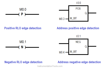
You will see that we are using a rising edge block before turning the light on. This is done because we are resetting the light in a flash style as required and again setting it. If we do not use this block, then the light will be set continuously as long as the sensor is on, and it will not reset.
This is the basis of SR or RS flip-flop logic (set-reset). Both the set and reset conditions should not remain on at the same time. Buzzer in our case is not an issue because it is anyways required to be continuously on.
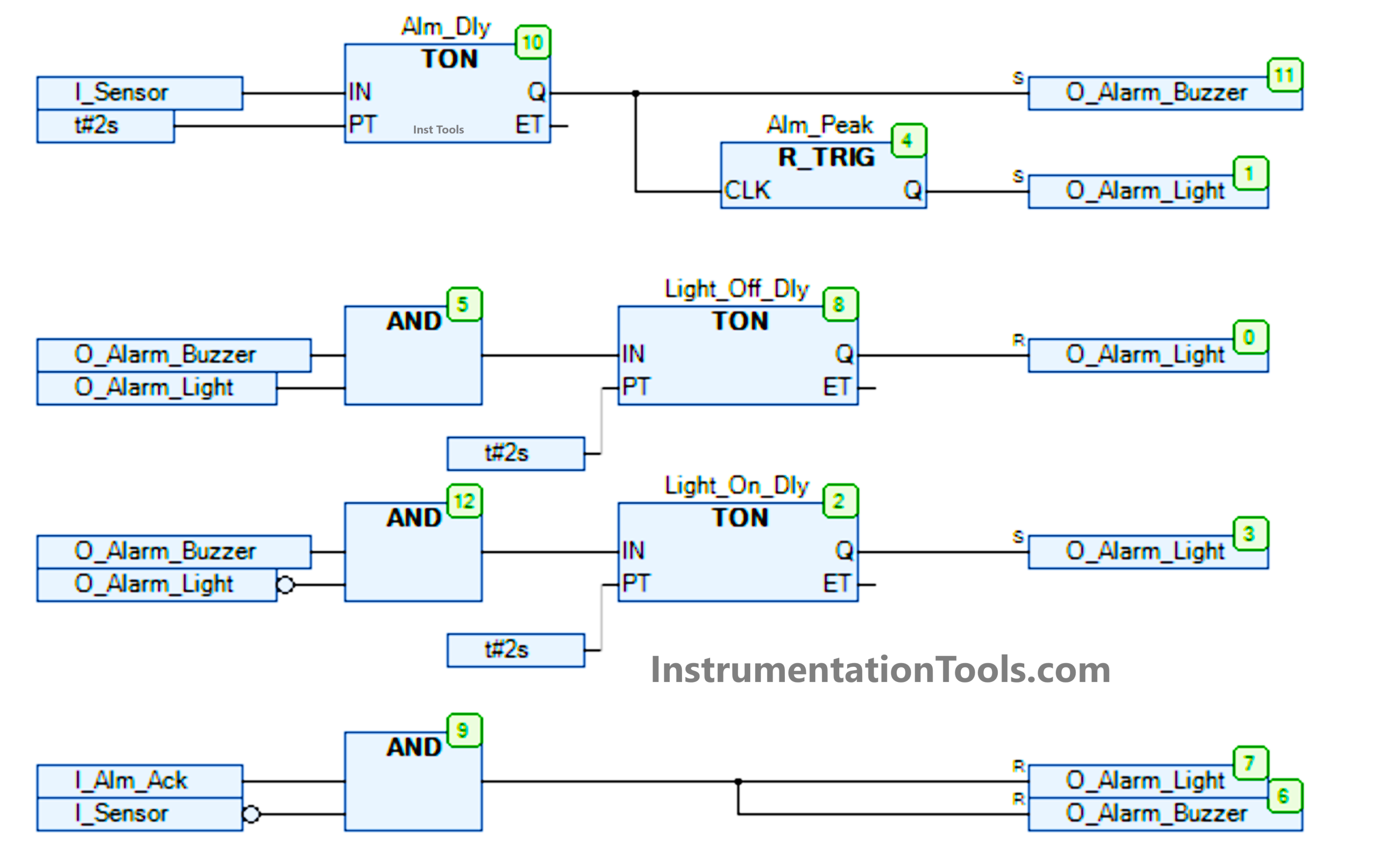
Now, after the alarm has been sensed, we use a flash logic for the lamp. In the second condition, we turn off the lamp after 2 seconds – the condition being both the buzzer and lamp are on first.
Then, in the third condition, we again turn on the lamp after 2 seconds – the condition being that the buzzer is on but the lamp is off (you can see a circle which denotes the negate condition). The logic will then continue to run in this fashion.
In the last state, we use a reset button to reset the outputs, also checking whether the sensor is off or not. If both the conditions are fulfilled, then only the outputs will turn off. So, if the sensor was on in that case, then our first condition would not be affected and the outputs too would remain on.
Then again, when the sensor is detected, the cycle repeats.
In this way, we saw how to write a burglar alarm security system using a functional block diagram.
Read Next:
- PLC Ladder Logic for Alarm Security System
- Allen Bradley PLC ControlLogix Hardware
- Quiz Program Logic Using PLC Programming
- Testing and Validation in PLC Development
- Face Mask Making Machine using PLC HMI