One of the most popular styles of single-fiber connector is the so-called “ST” style, which uses a quarter-turn locking barrel to secure the connector into its matching socket:
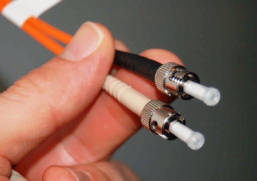
Communication patch cables such as the one shown above come in pairs of fibers, one for receiving and one for transmitting. Note how the plastic strain-relief grips between the metal barrel of each connector and each orange-jacketed cable are color-coded (one white, one black) for easy identification at each end of the cable.
An older style of connector based on the type used to connect small coaxial cables together is the “SMA” style, which used a threaded barrel to lock each fiber in place. The SMA-style connectors were very secure, but laborious to engage and disengage due to the fine pitch of the barrel’s threads and the subsequent need to turn the barrel multiple rotations (versus one-quarter turn of the barrel for an ST connector).
Given that communication patch cables typically have two fibers (one for each direction of data flow), connector styles have emerged to accommodate fiber pairs. One such style is the so-called “SC” connector, with a pair of side-by-side plugs accommodating twin optical fibers.
Terminating a bare cable of fibers with individual connectors is a time-consuming process, requiring the technician to unbundle the individual fibers, strip the jacketing off of each one to reveal the core and cladding, cleave each glass fiber to give it a flat end, and finally insert and secure each fiber into its respective connector. Typical fiber connectors use either a “hot-melt” or a chemical epoxy system of attachment, where the glue adheres to the strain-relief fibers of the cable for tensile strength, while the central glass fiber protrudes through a small hole in the center of the connector tip. This protruding glass fiber must be carefully cut and polished to produce a flat end suitable for engagement with another optical fiber aligned to its center.
Optical fibers may be spliced mid-way in a cable run, although this practice should be avoided whenever possible. If the fibers are multi-mode, the splicing may be done using “butt” connectors but the power losses may be unacceptable. Alternatively, stripped fibers may be inserted into both ends of a small-diameter tube filled with gel having the same index of refraction as the core glass, to “conduct” light with as little loss as possible from one fiber core to the other.
A very good technique often applied to single-mode fiber is that of fusion splicing, where two single-mode fiber ends are literally melted together using an electric arc so that they form one seamless glass fiber. The alignment of fibers prior to fusion is done under the view of a microscope, and often with the aid of a light source on one end and an optical power meter on the other end to give a quantitative measurement of alignment accuracy. When the two fibers are aligned as close as possible, the electric arc is fired to melt the two fibers together, creating a single fiber. Fusion splicing is the method of choice for long-distance runs of single-mode fiber, where low power loss and high integrity of the splice are paramount factors.
When laying optical fiber in wire trays, pulling through rigid conduit, or arranging it in connection panels, an important physical consideration is to maintain a minimum bend radius at all points along the fiber’s length. This is important because sharp bends will cause light to “leak” out of the fiber core and into the cladding where it may then escape the cable altogether. A sharp bend in an optical fiber will cause the angle between the light ray and the core/cladding interface to reach the critical point where total internal reflection no longer occurs:
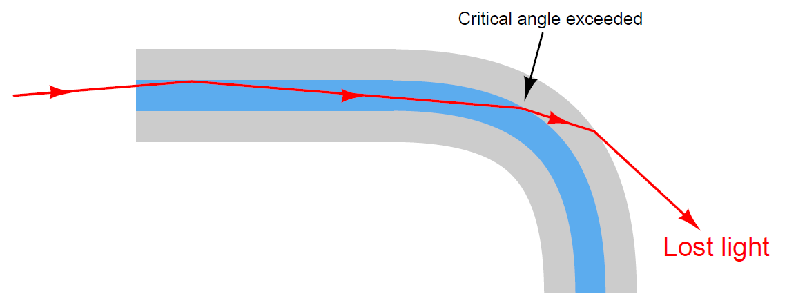
The light leakage from an optical fiber may be dramatic if the bend is sharp enough. On an indoor cable, using visible laser light, you can actually see the light “leak” through to the PVC outer coating on the outside of the cable!
Junction boxes and connection panels where excess lengths of fiber optic cabling may be coiled will typically provide plastic forms over which those loops of cable may be bent, the radius of that plastic form exceeding the manufacturer’s specification for minimum bend radius.
A common way in which the minimum bend radius requirement is violated is when a cable tie is used to anchor a fiber optic cable to some sturdy surface such as a wire tray or a cabinet post. The sharp bend created by the tension of a tightened cable tie on the fiber optic cable will easily exceed the minimum bend radius for that cable, creating light leakage and subsequent performance problems. Therefore, a good installation practice for fiber optic cables is to always leave cable ties loose enough that they do not tightly grip the cable.
There are multiple safety concerns when working with optical fibers, both when installing them and when doing maintenance-type work.
Installation hazards center around dangers of the glass fiber itself, while maintenance hazards center around the light sources used to “power” the optical fibers. Installation of fiber optic cable requires that individual glass fibers be separated from each other in a multi-fiber cable and each one terminated with a connector, and this requires at some point that the technician strip each fiber down to its glass core and cladding. Both the core and the cladding are extremely small in diameter, and are made of ultra-pure glass. If a piece of core/cladding breaks off the fiber and penetrates the skin, the resulting “sliver” will be nearly invisible due to its exceptional transparency. Its outer surface is also very smooth, making extraction difficult. Unextracted pieces of an optical fiber, if left in the body, can actually migrate through the victim’s flesh and become buried even deeper to the point where they can cause serious health problems. Technicians working with optical fiber typically lay a length of adhesive tape, sticky-side up, on whatever workbench or table they are using to prepare the cable, as a tool to catch any loose fiber ends they cut off. At the conclusion of the job, this length of tape is carefully rolled up and then disposed of in the same manner that “sharps” may be disposed of in a medical environment.
Maintenance technicians working with functioning fiber optic systems need to be careful when disconnecting “hot” fibers, due to the intensity of the light used in some systems. This is especially true of long-distance telecommunication fibers using laser sources rather than regular LEDs, which may have power levels reaching a half watt or so. One-half of a watt doesn’t sound like very much power, but when you consider this power level is concentrated over a circular area with a diameter less than 10 microns (for single-mode fiber), the watt-per-square-meter value is actually large enough to cause significant temperature increases wherever the light beam happens to fall. In fact, you can actually damage a fiber-optic connector on such a system by disconnecting the fiber with the fiber “powered”, the laser light being intense enough to burn and pit the aluminum ferrule of the connector!
Even standard LED light sources may pose a hazard if a technician directly views the end of the cable with his or her eyes, due to the focused nature of the light beam. The retina of your eye is extremely sensitive to light, and may easily be damaged by viewing such an intensely focused beam coming out of an optical fiber, where the entire LED’s light output is channeled into a core just a fraction of a millimeter in diameter. The optical hazard is even greater when infra-red light sources are used, because there is no visible indication of the light’s presence. A technician won’t even be able to see the light coming out, yet it could still be intense enough to damage their retina(s).
Laser-sourced fibers should never be unplugged from the equipment. One should treat a lasersourced fiber with the same respect as a “live” electrical circuit, and use the same lockout/tagout procedures to ensure personnel safety. In systems using visible light wavelengths, a safe way to view the light coming out the end of an optical fiber is to point the fiber end at a piece of paper and look for the colored dot falling on the paper. The paper’s rough surface scatters the light so that it is no longer a focused beam.
The only time it is truly safe to view the end of an optical fiber to check for light is when the light source is something diffuse such as natural sunlight or a flashlight. It is common for technicians to use a flashlight to identify fibers from one end of a multi-fiber cable to the other, one technician shining the flashlight at the end of one fiber while another technician views all the fibers at the other end of the cable to see which one is lit.
Some optical communications equipment come equipped with a feature called an Open Fiber Control (OFC) safety system, which turns off all light sources on a channel whenever an interruption of light is detected at the receiver port. Since most duplex (two-way) optical fiber channels consist of two fibers (one for each direction of light), a break in any one fiber will darken one receiver, which then commands the transmitter port on that equipment to darken as well to prevent anyone getting injured from the light. It also completely disrupts communication in that channel, requiring a re-initialization of the channel after the fiber is plugged back in.