The 4-20 mA current loop is a very robust sensor signaling standard. Current loops are ideal for data transmission because of their inherent insensitivity to electrical noise.
In a 4-20 mA current loop, all the signaling current flows through all components; the same current flows even if the wire terminations are less than perfect.
All the components in the loop drop voltage due to the signaling current flowing through them. The signaling current is not affected by these voltage drops as long as the power supply voltage is greater than the sum of the voltage drops around the loop at the maximum signaling current of 20 mA.
Basics of 4-20mA Current Loop

Figure 1 shows a schematic of the simplest 4-20 mA current loop.
There are mainly four components:
- A DC power supply;
- A 2-wire transmitter;
- A receiver resistor that converts the current signal to a voltage;
- The wire that interconnects it
The two “Rwire” symbols represent the resistance of the wires running out to the sensors and back to the power supply (Power supply means IO cards or barriers).

In Figure 1, current supplied from the power supply flows through the wire to the transmitter and the transmitter regulates the current flow within the loop. The current allowed by the transmitter is called the loop current and it is proportional to the parameter that is being measured.
The loop current flows back to the controller through the wire, and then flows through the Rreceiver resistor to ground and returns to the power supply(IO card or barrier).
The current flowing through Rreceiver produces a voltage that is easily measured by an analog input of a controller. For a 250Ω resistor, the voltage will be 1 VDC at 4 mA and 5 VDC at 20 mA.
4-20mA Current Loop Components:
1. The Power Supply
Power supplies for 2-wire transmitters must always be DC because the change in current flow represents the parameter that is being measured. If AC power were used, the current in the loop would be changing all the time.
Therefore, the change in current flow from the transmitter would be impossible to distinguish from change in current flow caused by the AC power supply.
For 4-20 mA loops with 2-wire transmitters, common power supply voltages are 36 VDC, 24 VDC, 15 VDC and 12 VDC.
Current loops using 3-wire transmitters can have either AC or DC power supplies. The most common AC power supply is the 24 VAC control transformer or 230A Ac.
Be sure to check any transmitter’s installation literature for the proper voltage requirements.
For a 2 wire transmitter the power supply is a IO card in System Cabinet or a Barrier in Marshalling Cabinet.
2. The Transmitter
The transmitter is the heart of the 4-20 mA signaling system.This is the device used to transmit data from a sensor over the two-wire current loop. There can be only one Transmitter output in any current loop. It acts like a variable resistor with respect to its input signal and is the key to the 4-20mA signal transmission system.
The transmitter converts the real world signal, such as flow, speed, position, level, temperature, humidity, pressure, etc., into the control signal necessary to regulate the flow of current in the current loop. The level of loop current is adjusted by the transmitter to be proportional to the actual sensor input signal.
An important distinction is that the transmitted signal is not the current in the loop, but rather the sensor signal it represents. The transmitter typically uses 4mA output to represent the calibrated zero input or 0%, and 20mA output to represent a calibrated full-scale input signal or 100%
Generally the power to transmitters as a range, 12 to 36 VDC The lower voltage is the minimum voltage necessary to guarantee proper transmitter operation. The higher voltage is the maximum voltage the transmitter can withstand and operate to its stated specifications.
A common misconception about Transmitters is that they source the loop current, but the transmitter is not the source of the current. Rather, it is a series connected current-sinking circuit that will attempt to draw current from a power supply wired to its output terminals.
The current in the loop is the medium via which the sensor signal is transmitted. The current flowing through the transmitter is proportional to the input signal being measured. When calibrated properly, this current will vary from 4 to 20mA over the range of its sensor input signal. The transmitter will also make allowances to support under-range and over-range output current levels.
3. The Receiver Resistor
It is much easier to measure a voltage than it is to measure a current. Therefore, many current loop circuits (such as the circuit in Figure 1) use a Receiver Resistor (Rreceiver) to convert the current into a voltage.
In Figure 1, Rreceiver is a 250Ω precision resistor. The current flowing through it produces a voltage that is easily measured by an analog input of a controller.
For the 250Ω resistor, the voltage will be 1 VDC at 4 mA of loop current and 5 VDC at 20 mA of loop current. The most common Receiver Resistor in a 4-20 mA loop is 250Ω; however, depending upon application, resistances of 100Ω to 750Ω may be used.
4. The Wire
The impact of the wire resistance in the current loop is often ignored, as it usually contributes negligible voltage drop over short distances and small installations.
However, over long transmission distances, this drop can be significant and must be accounted for, as some current loop installations will use wire distributed over hundreds and even thousands of feet.
To illustrate the impact of wire resistance, the following table lists the resistance of common copper wire gauges.
Sending current through a wire produces a voltage drop proportional to the length and thickness (gauge) of the wire. Generally 1.5 Sqmm thickness cable will be preferred, However depending on the application or plant design 0.5 Sqmm, 2.5 Sqmm, 3Sqmm, 6Sqmm etc… will also be used.
All wire has resistance, usually expressed in Ohms per 1,000 feet.
The voltage drop can be calculated using Ohm’s law:
E = I x R
E = the voltage across the resistor in volts;
I =the current flowing through the conductor in amperes;
R = the conductor’s resistance in Ohms.
Wire resistances for common wire gauges are shown in Table 1 above.
As an example of the potential impact wire resistance can have on an installation, let’s assume that we have wired our loop elements together using 3000 feet of 24 AWG. Note that 3000 feet is the total round-trip length of wire. Thus, we can calculate a wire resistance of 3000ft*26.2Ω/1000ft =78.6Ω. This will result in a voltage drop of 0.022A* 78.6Ω =1.73V at a maximum loop current of 22mA.
If you find yourself having to do these kinds of calculations often, but you do not have an AWG Copper Wire Chart handy, you can approximate the wire resistance of a given gauge by committing three points to memory:
40 AWG copper wire is approximately 1Ω per foot (refer to Table 1 and see 40AWG is 1070Ω per 1000 feet, or 1.07Ω per foot).
Every 10 wire gauges lower divides resistance by 10 (refer to Table 1 and note that 30AWG is 105.2Ω per 1000 feet, or 0.1Ω per foot).
Every 3 wire gauges lower halves the resistance.
For example, to approximate the resistance of 24AWG copper wire, without having to refer to a table, you can do the math in your head as follows:
Remembering that 40AWG is 1Ω/foot. Then 10AWG lower is 30AWG and one-tenth of this, or 0.1Ω/foot. Then 3 AWG lower is 27AWG at one half of this, or 0.05Ω/foot. Then 3 AWG lower at 24AWG is one half of that, or 0.025Ω/foot.
Now check this against Table 1 and note that 24AWG wire is actually 26.17Ω per 1000 feet, or 0.02617Ω per foot. Our approximation is less than 5% from the value in Table 1. You will note slight differences in wire resistance values from manufacturer to manufacturer.
Insensitivity to Electrical Noise
The greatest advantage of using a current loop for data transmission is a current loop’s inherent insensitivity to electrical noise. Every transmitter has some output resistance associated with it.
Ideally, the current transmitter’s output resistance would be infinite. However, real world transmitters have very large but not infinite output resistances.This output resistance can be represented as a resistor in a circuit schematic.
The circuit schematic at right (Figure 2) shows the component resistances of a 4-20 mA current loop with a noise source added to the loop.
Because of the high output resistance of the transmitter(3.64MegΩ), the vast majority of the noise voltage is dropped across the transmitter, and only a tiny fraction is dropped across the Rreceiver. Since the controller sees only the voltage across the Rreceiver, the noise voltage has almost no effect upon the controller.
Current Loop Noise Reduction Example:
If the noise source in Figure 2 has an amplitude of 20 Volts, then the noise voltage seen across the Rreceiver is only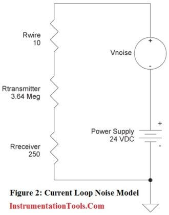 0.0014 volts. This is because the noise voltage measured across any resistor is equal to the Ohms of that resistor divided by the total Ohms in the circuit multiplied by the noise voltage.
Voltage Noise at Rreceiver =
Vnoise x Rreceiver/(Rwire+Rtransmitter+Rreceiver)
Vnoise = 20 x 250/3,640,260 = 0.0014 volts
The voltage across Rreceiver at 20 mA of loop current is five volts. Adding 0.0014 volts of noise is only 0.028% of five volts, which is an insignificant error.
If the power supply of Figure 1 is varied such that the voltage dropped across the transmitter varies from 7 to 24 VDC, the output current only changes by 0.000005 amps, or 5 micro-amps. This equals only 0.00125 volts across the 250Ω Rreceiver resistor, which is an insignificant fluctation.
What makes 4-20mA signal transmission so attractive?
While we’ve reviewed some of the fundamentals of 4-20mA two-wire current loops and the basic loop elements, and we have an idea of how they work together, let’s consider some of the advantages of 4-20mA signal transmission.
Probably the greatest advantage of using a current loop for signal transmission is the current loop’s low sensitivity to electrical noise. This is very important for long distance transmission in harsh industrial environments. As a generally low impedance system, it is much less sensitive to induced noise, than perhaps the high impedance input of a voltage amplifier.
The currents injected by typical noise sources are generally no more than a few hundred micro-amps, usually insignificant to the 16mA span. The use of a “Live Zero” also improves the signal to noise ratio at low levels, allowing us to accurately discern low signal levels without added noise or interference.
Another advantage to the 4-20mA current loop is that it is essentially lossless with respect to the transmission media (wire) and the interconnections (connectors). That is, the accuracy of the signal is not affected by the voltage drop in the interconnecting wiring. This allows the signal transmission to occur over long distances, with varying conductors.
Compare this to voltage signals, which will always have an associated signal loss related to the length of the wires— the 4-20mA signal current does not exhibit any signal losses under this same scenario. Kirchoff’s Current Law teaches us that the current in a loop is equivalent at any point in the loop. That is, if you happen to be reading 12mA at your receiver input, you can be certain that 12mA is passing through your transmitter.
The 4mA “Zero-Offset”, “Live Zero”, or “Positive-Zero” is Failsafe. The use of 4mA as the starting point for our transmitted signal is useful in trouble-shooting, as signal integrity is verified with 0% of input and output signal.
A failed current loop due to a lead break or open device can be immediately discerned as zero current flow, which is a fail-safe level outside of the signal range. By offsetting the signal from zero, some transmitters will define an alarm limit just below 4mA and different from zero, allowing a receiver to detect other failures in the system, like an input sensor lead break.
Having a live zero in your control system also allows you to set the “zero” of your controlled device (i.e. an actuator valve or other device) just a little bit below 4mA to hold it completely OFF. You wouldn’t be able to do that with a zero-based 0-20mA output. A “Live Zero” of 4mA also permits the two-wire current loop to power the transmitter, simplifying installation and reducing costs.
The 4-20mA current loop also allows additional “Receiver” devices to be connected in series in the loop without a loss of signal. That is, as long as the loop voltage supply has sufficient capacity to drive the additional IR voltage drops of the added devices, and its voltage does not exceed the maximum voltage rating of the transmitter.
For example, you might choose to wire a panel meter, a trend recorder, and a PLC input card in series in the same current loop. The loop transmitter will maintain proper current in the loop, up to the voltage capability of the loop. The number of additional receiver devices you can add is only limited by the available voltage level.
The 4-20mA transmission standard also has low inherent energy, minimizing its ability to couple noise into other systems and also reducing its radiated emissions. Contrast that to the older pneumatic systems that use inefficient high power compressors up to 50HP to drive compressed air through their control lines.
Also Read: 4-20mA Analog Current Signals


Thanks for sharing knowledge on 4-20mA current loops.
Awesome lecture ! Got what I expected . superb explanation..
Nice to recollect through SMART phone…
Great notes.. Too easy to understand and it seems interesting ..
Respectd, Bhardwaj ji.
i m a I&C engineer..i very appriciate Ur This Work Of ” inst. tool ” site update….!!!
Thanks Behalf of All Users…..
Thank you Rushi Amin for your encouraging comments.
hi
what not language translate to mozilla firefox?
Hello Towraj, Language Translator is inbuilt Feature of InstrumentationTools.com Website. You can find this option in right side of website. You donot require any additional plugin in mozilla or other browsers. Also update mozilla if you are facing any problem or try other browser.Thank You.
Wonderful info. lots of generators are using this for example generac has a color coated 4 to 20ma converter for each sensor, like water temp, oil pressure, water level ect. one of the most important tools is my 1000ohm resistor to jump out a bad sensor to keep the unit running in a emergency. of course if its a important sensor it would need to be monitered if it absolutly needs to run and the parts not avail. Otherwise we would leave tge unit off until the part arrives. Unfortunantly if its a hospital the unit has to run.
I am an instrument technician in an oil refinery in Ghana and I must say this site is indeed a refresher platform/tool for me. Thanks to all the team who made and continue to make it very informative. God bless you all.
Thank you admins and moderators of this site. You guys are doing awesome job in sharing these basics of instrumentation engineering. Thank you very much and may god bless you and your families.
Sir,
thanks for your help.
please add articles about weigh feeder.
Thank you very much for sharing the info. It is indeed a refresher