This is a complex ladder logic PLC examples for automatic sanitizer. The sanitization process runs when the door is used as per the program.
Note: The PLC ladder logic is considered a resource for learning the PLC fundamentals.
Automatic Sanitizer
Problem Statement:
Design a PLC ladder logic for the following application.
We are using one Push Button to control Sanitizer.
The sanitization process should run for 10 seconds when the door is used 4 times.
Complex Ladder Logic PLC Examples
This PLC video explains the complex ladder logic in an easy explanation and simple way.
Inputs and Outputs
Digital Inputs:
Unlock Button: I0.0
Digital Outputs:
Sanitizer: Q0.0
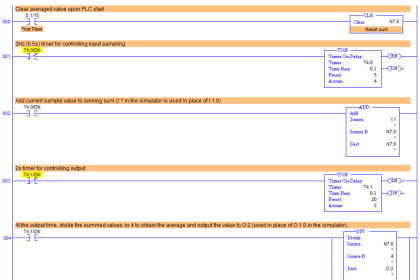
PLC Programming
Program Explained
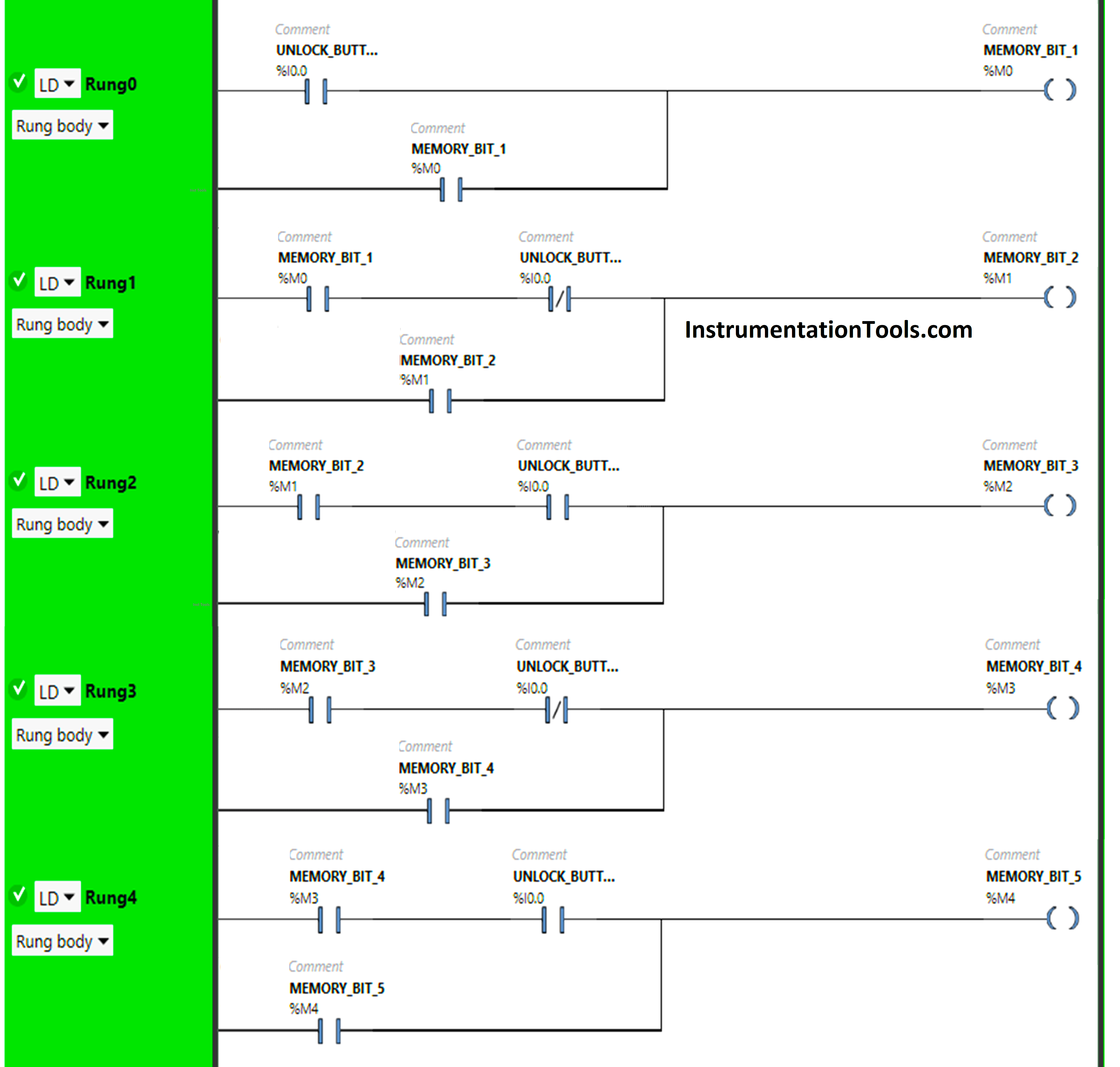
We have used Normally Open Contacts for the Unlock Button(I0.0) and Memory Bits.
We have used Normally Closed Contacts for Unlock Button (I0.0).
In Rung 0:
- Normally Open Contact is used for the Unlock Button(I0.0) to Turn ON Memory Bit 1 (M0).
- Memory Bit 1 (M0) is latched so that when the Unlock Button(I0.0) turns OFF, Memory Bit 1 (M0) still remains ON.
In Rung 1:
- Normally Open Contact is used for Memory Bit 1 (M0) to Turn ON Memory Bit 2 (M1).
- Normally Closed Contact is used for Unlock Button (I0.0) to Turn ON Memory Bit 2 (M1).
- Memory Bit 2 (M1) is latched so that when Memory Bit 1 (M0) turns OFF, Memory Bit 2 (M1) still remains ON.
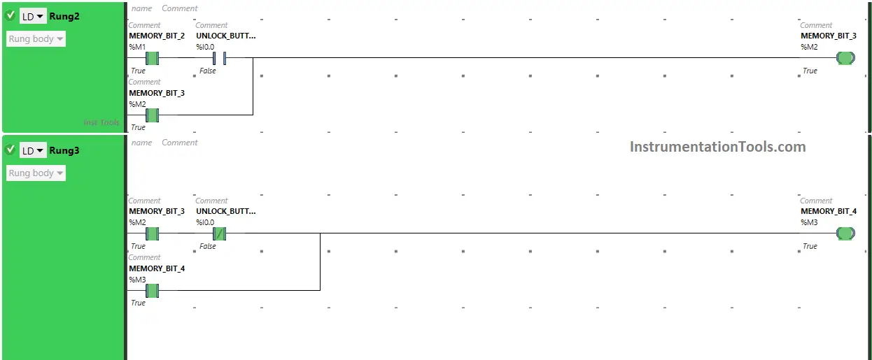
In Rung 2:
- Normally Open Contacts are used for Unlock Button (I0.0) and Memory Bit 2 (M1) to turn ON Memory Bit 3 (M2).
- Memory Bit 3 (M2) is latched so that when the Unlock Button (I0.0) or Memory Bit 2 (M1) turns OFF, Memory Bit 3 (M2) still remains ON.
In Rung 3:
- Normally Open Contact is used for Memory Bit 3 (M2) to Turn ON Memory Bit 4 (M3).
- Normally Closed Contact is used for Unlock Button (I0.0) to Turn ON Memory Bit 4 (M3).
- Memory Bit 4 (M3) is latched so that when Memory Bit 3 (M2) turns OFF, Memory Bit 4 (M3) still remains ON.
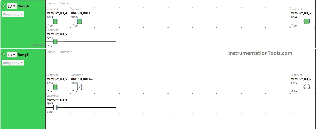
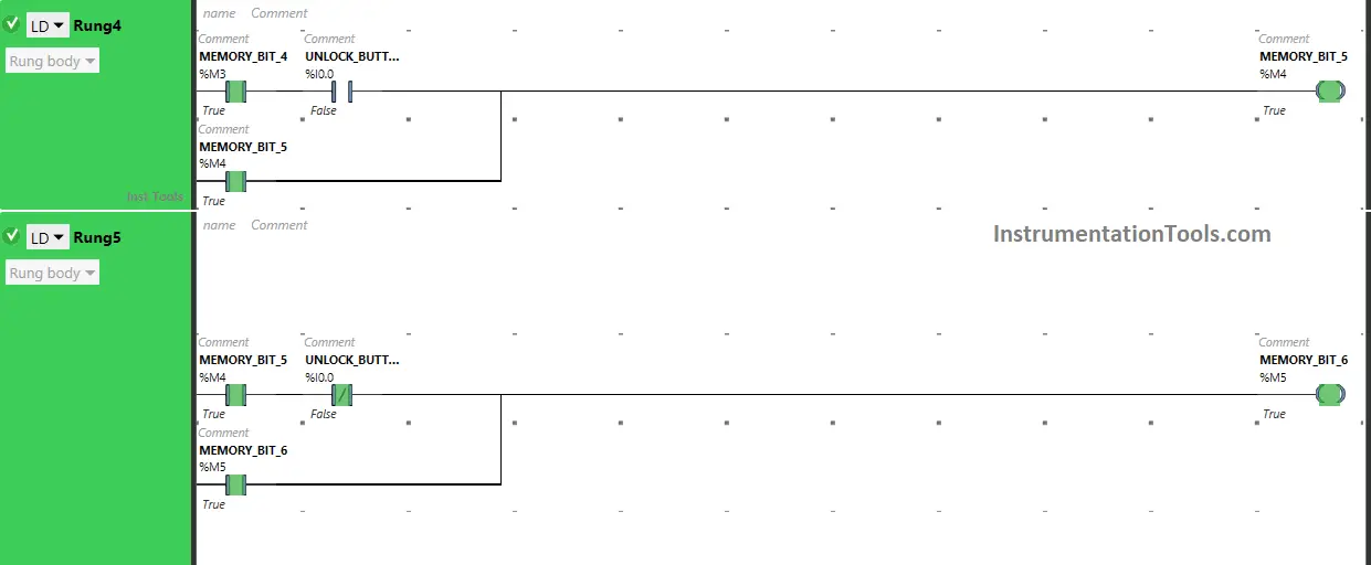
In Rung 4:
- Normally Open Contacts are used for Unlock Button(I0.0) and Memory Bit 4 (M3) to turn ON Memory Bit 5 (M4).
- Memory Bit 5 (M4) is latched so that when the Unlock Button(I0.0) or Memory Bit 4 (M3) turns OFF, Memory Bit 5 (M4) still remains ON.
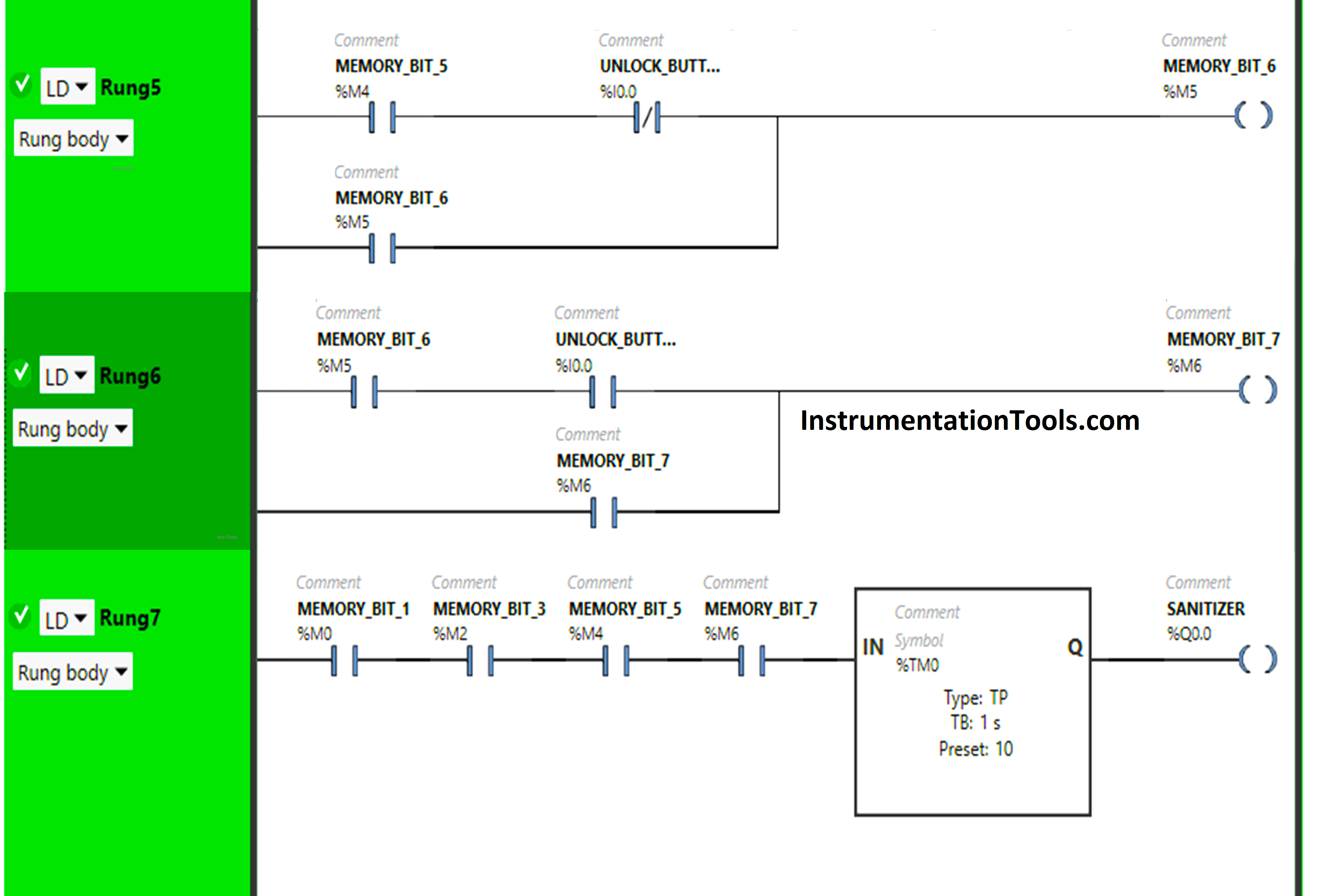
In Rung 5:
- Normally Open Contact is used for Memory Bit 5 (M4) to Turn ON Memory Bit 6 (M5).
- Normally Closed Contact is used for Unlock Button (I0.0) to Turn ON Memory Bit 6 (M5).
- Memory Bit 6 (M5) is latched so that when Memory Bit 5 (M4) turns OFF, Memory Bit 6 (M5) still remains ON.
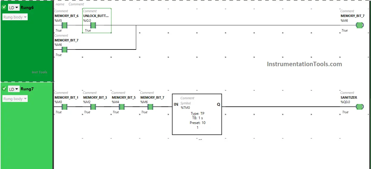
In Rung 6:
- Normally Open Contacts are used for Unlock Button (I0.0) and Memory Bit 6 (M5) to turn ON Memory Bit 7 (M6).
- Memory Bit 7 (M6) is latched so that when the Unlock Button (I0.0) or Memory Bit 7 (M6) turns OFF, Memory Bit 7 (M6) still remains ON.
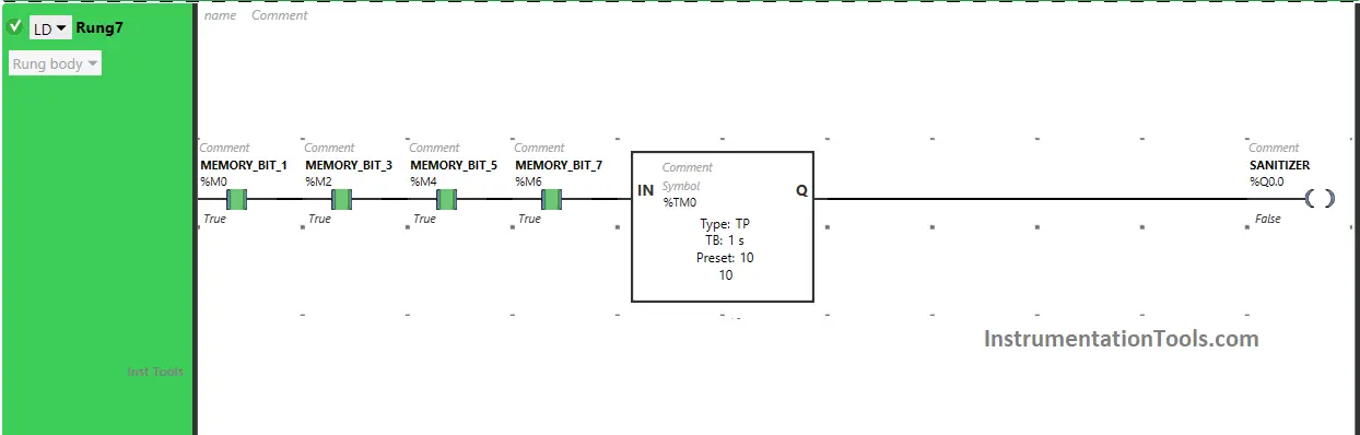
In Rung 7:
- Normally Open Contact is used for Memory Bit 1 (M0), Memory Bit 3 (M2), Memory Bit 5 (M4), and Memory Bit 7 (M6) to Turn ON the output Sanitizer (Q0.0).
- Timer-type TP is used to Turn ON the output Sanitizer (Q0.0) for a limited time.
Simulation Results
Now we simulate the PLC program and discuss the test cases. We may show the part of the logic or rung in the test cases instead of the complete code.
We recommend watching the above PLC programming video for better learning concepts.
When the Unlock Button is pressed and released the first time
When the Unlock Button (I0.0) is pressed the first time (When the door is opened and closed the first time), Memory Bit 1 (M0) turns ON and stores the data that the Unlock Button (I0.0) is pressed the first time or (Door is opened the first time) as Memory bits stores the data.
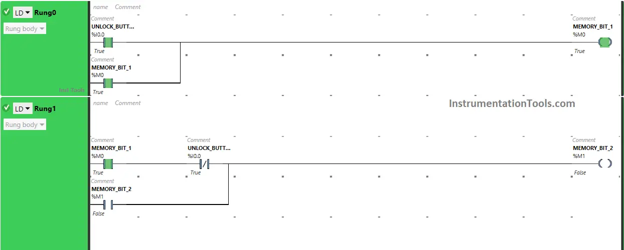
Memory Bit 1 (M0) is latched so that when the Unlock Button (I0.0) is released, Memory Bit 1 (M0) still remains ON. When the Unlock Button (I0.0) is released first time in Rung0.
Normally Closed Contact used for the Unlock Button (I0.0) in Rung1 will be in a false state and will pass the signal to turn ON Memory Bit 2 (M1).
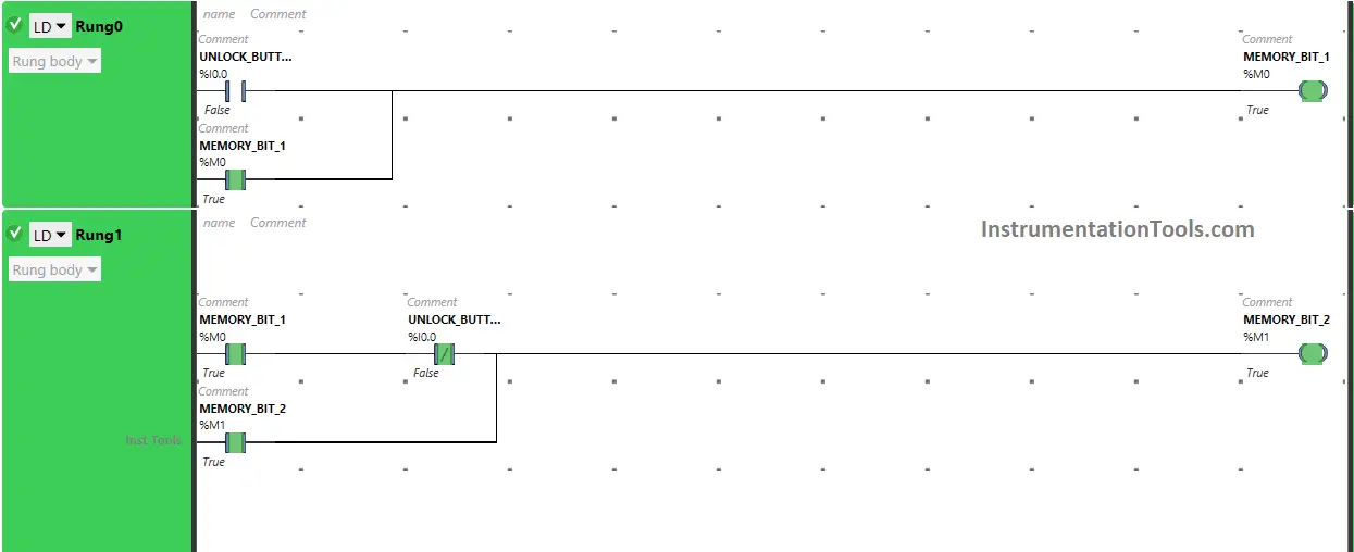
Also, When Memory Bit 1 (M0) turns ON in Rung0, Normally Open Contact used for Memory Bit 1 (M0) in Rung1 will be in True State and will pass the signal to turn ON Memory Bit 2 (M1), and Memory Bit 2 (M1) will turn ON in Rung1.
Memory Bit 2 (M1) will store the data that the Unlock Button (I0.0) is released the first time or (The door is closed the first time). Memory Bit 2 (M1) is latched so that when Memory Bit 1 (M0) turns OFF, Memory Bit 2 (M1) still remains ON.
When the Unlock Button is pressed and released the Second time
When the Unlock Button (I0.0) is pressed the Second time (When the door is opened and closed the Second time), Memory Bit 3 (M2) turns ON as Normally Open Contact used for the Unlock Button (I0.0) will be in a True state and will pass the signal to turn ON Memory Bit 3 (M2).
When Memory Bit 2 (M1) turns ON in Rung1, Normally Open Contact used for Memory Bit 2 (M1) in Rung2 will be in a True state and will also pass the signal to turn ON Memory Bit 3 (M2), and Memory Bit 3 (M2) will turn ON.
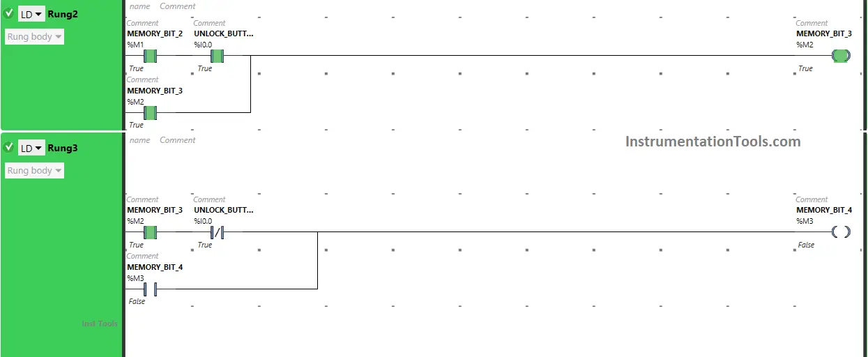
Memory Bit 3 (M2) stores the data that the Unlock Button (I0.0) is pressed the Second time or (The door is opened the Second time) as Memory Bit stores the data. Memory Bit 3 (M2) is latched so that when the Unlock Button (I0.0) is released, Memory Bit 3 (M2) still remains ON.
When the Unlock Button (I0.0) is released the Second time, the Normally Closed Contact used for the Unlock Button (I0.0) in Rung3 will be in a false state and will pass the signal to turn ON Memory Bit 4 (M3).
Also, When Memory Bit 3 (M2) turns ON in Rung2, Normally Open Contact used for Memory Bit 3 (M2) in Rung3 will be in True State and will pass the signal to turn ON Memory Bit 4 (M3), and Memory Bit 4 (M3) will turn ON in Rung3.
Memory Bit 4 (M3) will store the data that the Unlock Button (I0.0) is released the Second time or (The door is closed the Second time). Memory Bit 4 (M3) is latched so that when Memory Bit 3 (M2) turns OFF, Memory Bit 4 (M3) still remains ON.
When the Unlock Button is pressed and released a third time
When the Unlock Button (I0.0) is pressed a third time (When the door is opened and closed a third time), Memory Bit 5 (M4) turns ON as Normally Open Contact used for Unlock Button (I0.0) will be in True state, and will pass the signal to turn On Memory Bit 5 (M4).
When Memory Bit 4 (M3) turns ON in Rung3, Normally Open Contact used for Memory Bit 4 (M3) in Rung4 will be in a True state and will also pass the signal to turn ON Memory Bit 5 (M4), and Memory Bit 5 (M4) will turn ON.
Memory Bit 5 (M4) stores the data that the Unlock Button (I0.0) is pressed a third time or (The door is opened a third time) as Memory bits store the data. Memory Bit 5 (M4) is latched so that when Unlock Button (I0.0) is released, Memory Bit 5 (M4) still remains ON.
When the Unlock Button (I0.0) is released the third time, Normally Closed Contact used for the Unlock Button (I0.0) in Rung5 will be in a false state and will pass the signal to turn ON Memory Bit 6 (M5).
Also, When Memory Bit 5 (M4) turns ON in Rung4, Normally Open Contact used for Memory Bit 5 (M4) in Rung5 will be in True State and will pass the signal to turn ON Memory Bit 6 (M5), and Memory Bit 6 (M5) will turn ON in Rung5.
Memory Bit 6 (M5) will store the data that the Unlock Button (I0.0) is released a third time or (The door is closed a third time). Memory Bit 6 (M5) is latched so that when Memory Bit 5 (M4) turns OFF, Memory Bit 6 (M5) still remains ON.
When the Unlock Button is pressed a fourth time
When the Unlock Button (I0.0) is pressed the fourth time (When the door is opened a fourth time), Memory Bit 7 (M6) turns ON as Normally Open Contact used for the Unlock Button (I0.0) will be in True state and will pass the signal to turn ON Memory Bit 7 (M6).
When Memory Bit 6 (M5) turns ON in Rung5, Normally Open Contact used for Memory Bit 6 (M5) in Rung6 will be in True state and will also pass the signal to turn ON Memory Bit 7 (M6) and Memory Bit 7 (M6) will turn ON.
Memory Bit 7 (M6) stores the data that the Unlock Button (I0.0) is pressed a fourth time or the door is opened a fourth time) as Memory bits stores the data. Memory Bit 7 (M6) is latched so that when the Unlock Button (I0.0) is released, Memory Bit 7 (M6) still remains ON.
Also, when Memory Bit 1 (M0) turns ON in Rung0, Memory Bit 3 (M2) turns ON in Rung2, Memory Bit 5 (M4) turn ON in Rung4, Memory Bit 7 (M6) turn ON in Rung6 or Door opens four times.
Normally Open Contact used for Memory Bit 1 (M0), Memory Bit 3 (M2), Memory Bit 5 (M4), and Memory Bit 7 (M6) in Rung7 will be in True State and will pass the signal to turn ON the output Sanitizer (Q0.0).
The output Sanitizer (Q0.0) will turn ON for 10 seconds as Timer Function Block type TP is used to turn ON the output Sanitizer (Q0.0) for Limited time. The time is set to 10 seconds. After 10 seconds, the output sanitizer (Q0.0) will turn OFF.
If you liked this article, please subscribe to our YouTube Channel for PLC and SCADA video tutorials.
You can also follow us on Facebook and Twitter to receive daily updates.
Read Next:
- Complex PLC Test Bench Programming
- Traffic Lights PLC Program using Timers
- Parking Lights PLC Program Explained
- PLC Program for the Pump to fill the tank
- PLC Programming of Switch Program