This is a complex PLC programming example on an automated test bench to carry out 3 tests sequentially when the specimen is placed on the bench.
Note: This PLC program was created for the persons to learn the PLC basics.
Automated Test Bench
Problem Statement:
Design a PLC ladder logic for the following application.
We are using one toggle switch and one sensor to control 3 Tests.
When a test specimen is placed on the bench, a series of 3 tests should run sequentially, each lasting for 10 seconds. The time delay between the two tests should be 5 seconds.
Complex PLC Programming Examples
Instrumentation Tools provides you the complex PLC example programs for practicing the ladder logics.
This PLC video explains the test bench PLC programming in a detailed explanation.
List of I/Os
Digital Inputs:
Start Button: I0.0
Sensor: I0.1
Digital Outputs:
Test 1: Q0.0
Test 2: Q0.1
Test 3: Q0.2
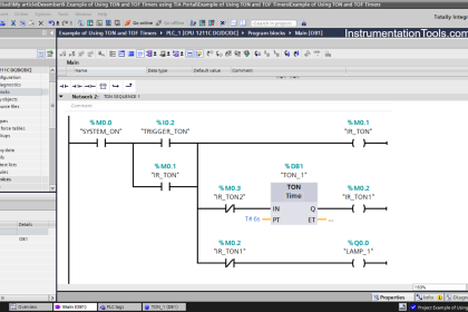
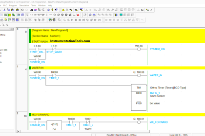
Ladder Logic
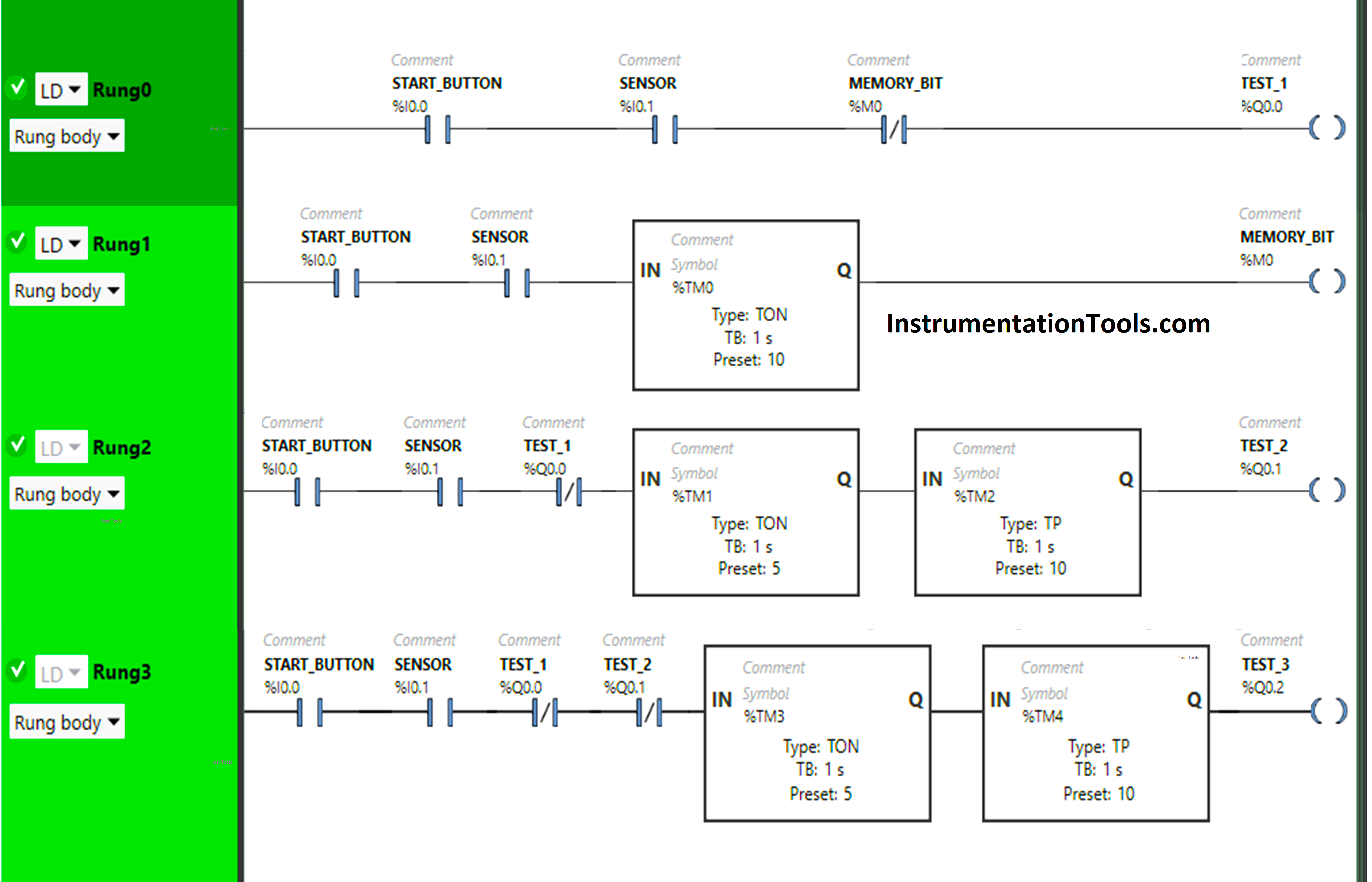
Program Description
We have used Normally Open Contacts for Start Button( I0.0) and Sensor (I0.1).
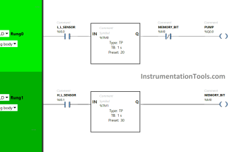
In Rung 0:
- Normally Open Contacts are used for the Start Button (I0.0) and Sensor (I0.1) to Turn ON the output Test 1 (Q0.0).
- Normally Closed Contact is used for Memory Bit (M0) to turn OFF the output Test 1 (Q0.0).
In Rung 1:
- Normally Open Contacts are used for the Start Button (I0.0) and Sensor (I0.1) to Turn ON Memory Bit (M0).
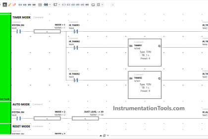
- Timer-type TON is used to delay the turning ON time of Memory Bit (M0) for some time.
In Rung 2:
- Normally Open Contacts are used for the Start Button (I0.0) and Sensor (I0.1) to Turn ON the output Test 2 (Q0.1).
- Normally Closed Contact is used for Test 1 (Q0.0) to turn ON the output Test 2 (Q0.1).
- Timer Function Block type TON is used to delay the turning ON time of the output Test 2 (Q0.1) for some time.
- Timer Function Block type TP is used to Turn ON the output Test 2(Q0.1) for a limited time.
In Rung 3:
- Normally Open Contacts are used for the Start Button (I0.0) and Sensor (I0.1) to Turn ON the output Test 3 (Q0.2).
- Normally Closed Contacts are used for Test 1 (Q0.0) and Test 2 (Q0.1) to turn ON the output Test 3 (Q0.2).
- Timer-type TON is used to delay the turning ON time of the output Test 3 (Q0.2) for some time.
- Timer-type TP is used to Turn ON the output Test 3 (Q0.2) for a limited time.
Simulation of Logic
We will simulate our PLC logic and analyze the results. We may show the part of the logic instead of the complete code.
Rung 0:
When the Start Button (I0.0) is turned ON and Sensor (I0.1) gets activated (Sensor detects test), the output Test 1 (Q0.0) turns ON (Tests 1 starts) as Normally Open Contact used for Start Button (I0.0) and sensor (I0.1) allows the signal to pass through it to turn ON the output Test 1 (Q0.0).
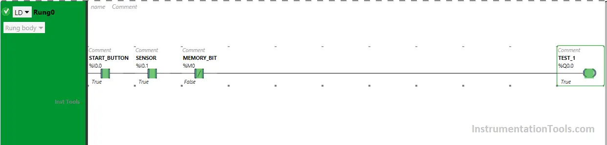
In a false state, Normally Closed Contact used for Memory Bit (M0) also passes the signal to turn ON the output Test 1 (Q0.0) and the output Test 1 (Q0.0) turns ON.
Rung 1:
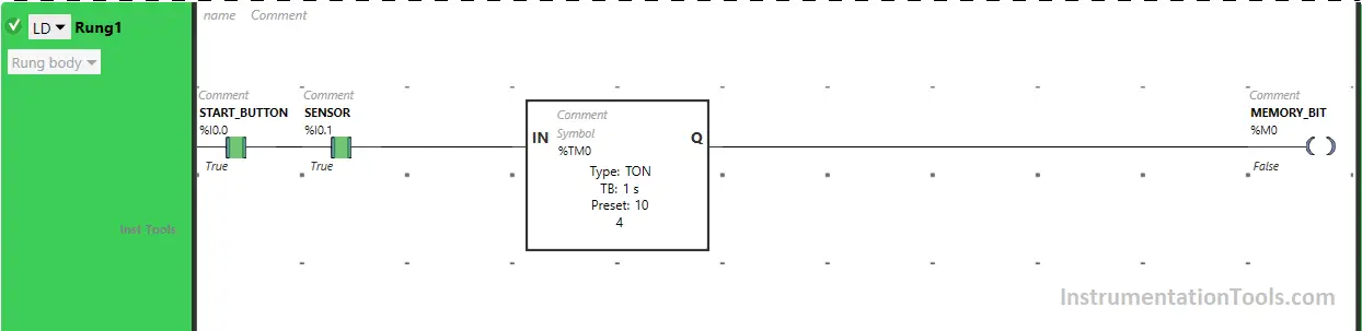
Also, When the Start Button (I0.0) is turned ON and Sensor (I0.1) gets activated (Sensor detects test).
Memory Bit (M0) turns ON after 10 seconds as Timer Function Block type TON is used to delay the turning ON time of Memory Bit (M0) and the time is set to 10 seconds.
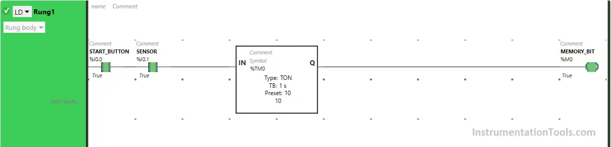
So after 10 seconds, Memory Bit (M0) will turn ON.
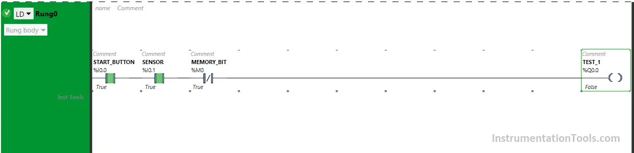
When Memory Bit (M0) turns ON in Rung1, Normally Closed Contact used for Memory Bit (M0) in Rung0 will be in True State and does not allow the signal to flow through it and the output Test 1 (Q0.0) in Rung0 will Turn OFF (Test 1 Ends).
Rung 2:
When Start Button (I0.0) is turned ON, Sensor (I0.1) gets activated (Sensor detects test) and the output Test 1 (Q0.0) turns OFF in Rung0 (Test 1 Ends), the output Test 2 (Q0.1) turns ON because when the output Test 1 (Q0.0) turns OFF in Rung0.
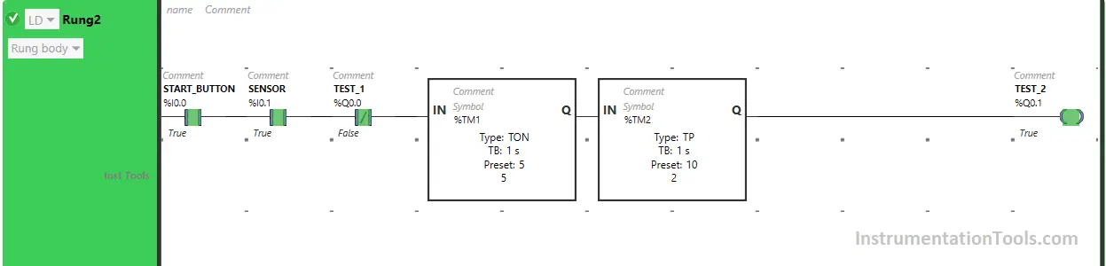
Normally Closed Contact used for Test 1 (Q0.0) in Rung2 will be in a False state and allow the signal to pass through it.
The output Test 2 (Q0.1) will turn ON but after 5 seconds (Test 2 starts after 5 seconds) as Timer Function Block type TON is used to delay the turning ON time of the output Test 2 (Q0.1) and the time is set to 5 seconds.
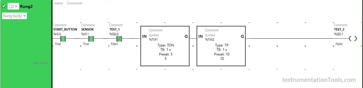
So after 5 seconds, the output Test 2 (Q0.1) will turn ON (Test 2 starts) but only for 10 seconds as we have used Timer Function Block type TP to turn ON the output Test 2 (Q0.1) only for a limited time and the time is set to 10 seconds.
So after 10 seconds, the output Test 2 (Q0.1) will turn OFF (Test 2 Ends).
Rung 3:
When Start Button (I0.0) is turned ON, Sensor (I0.1) gets activated (Sensor detects test), the output Test 1 (Q0.0) turns OFF in Rung0 (Test 1 is Ended) and the output Test 2 (Q0.1) turns OFF in Rung2 (Test 2 is Ended).
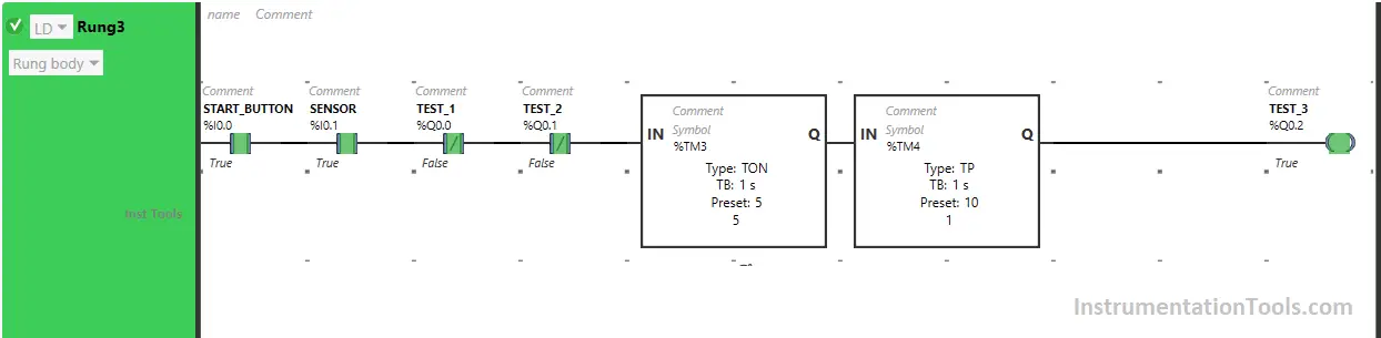
The output Test 3 (Q0.2) turns ON because when the output Test 1 (Q0.0) turns OFF in Rung0 and the output Test 2 (Q0.1) turns OFF in Rung2, Normally Closed Contact used for Test 1 (Q0.0) and Test 2 (Q0.1) in Rung3 will be in False state.
This allows the signal to pass through it and the output Test 3 (Q0.2) will turn ON but after 5 seconds (Test 3 starts after 5 seconds) as Timer Function Block type TON is used to delay the turning ON time of the output Test 3 (Q0.2) and the time is set to 5 seconds.
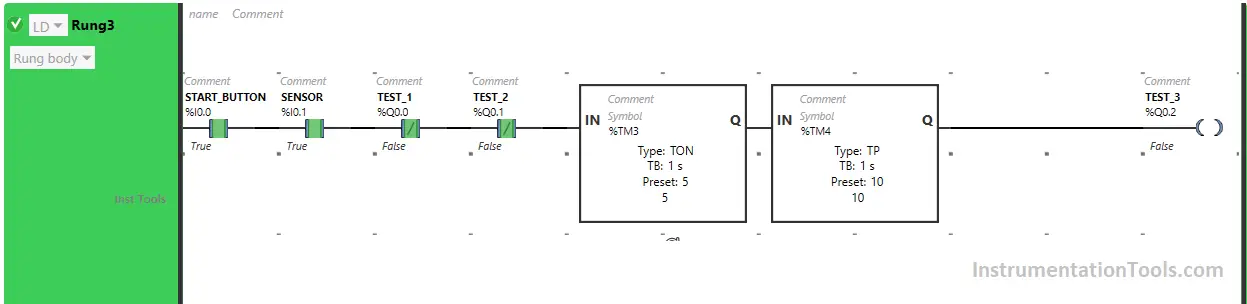
So after 5 seconds, the output Test 3 (Q0.2) will turn ON (Test 3 starts) but only for 10 seconds as we have used Timer Function Block type TP to turn ON the output Test 3 (Q0.2) only for a limited time and the time is set to 10 seconds.
So after 10 seconds, the output Test 3 (Q0.2) will turn OFF (Test 3 Ends).
If you liked this article, please subscribe to our YouTube Channel for PLC and SCADA video tutorials.
You can also follow us on Facebook and Twitter to receive daily updates.
Read Next:
- Traffic Lights PLC Program using Timers
- Heater and Cooler PLC Exercise Problem
- PLC Programming for Trash Compactor
- Playground Swing PLC Logic Programming
- PLC Programming for the Pump to fill the tank