Inst ToolsInst ToolsInst Tools
  • Courses
  • Automation
    • PLC
    • Control System
    • Safety System
    • Communication
    • Fire & Gas System
  • Instrumentation
    • Design
    • Pressure
    • Temperature
    • Flow
    • Level
    • Vibration
    • Analyzer
    • Control Valve
    • Switch
    • Calibration
    • Erection & Commissioning
  • Interview
    • Instrumentation
    • Electrical
    • Electronics
    • Practical
  • Q&A
    • Instrumentation
    • Control System
    • Electrical
    • Electronics
    • Analog Electronics
    • Digital Electronics
    • Power Electronics
    • Microprocessor
  • Request
Search
  • Books
  • Software
  • Projects
  • Process
  • Tools
  • Basics
  • Formula
  • Power Plant
  • Root Cause Analysis
  • Electrical Basics
  • Animation
  • Standards
  • 4-20 mA Course
  • Siemens PLC Course
Reading: Always ON and OFF Bit using Ladder Logic and Statement List
Share
Font ResizerAa
Inst ToolsInst Tools
Font ResizerAa
  • Courses
  • Design
  • PLC
  • Interview
  • Control System
Search
  • Courses
  • Automation
    • PLC
    • Control System
    • Safety System
    • Communication
    • Fire & Gas System
  • Instrumentation
    • Design
    • Pressure
    • Temperature
    • Flow
    • Level
    • Vibration
    • Analyzer
    • Control Valve
    • Switch
    • Calibration
    • Erection & Commissioning
  • Interview
    • Instrumentation
    • Electrical
    • Electronics
    • Practical
  • Q&A
    • Instrumentation
    • Control System
    • Electrical
    • Electronics
    • Analog Electronics
    • Digital Electronics
    • Power Electronics
    • Microprocessor
  • Request
Follow US
All rights reserved. Reproduction in whole or in part without written permission is prohibited.
Inst Tools > Blog > PLC Tutorials > Always ON and OFF Bit using Ladder Logic and Statement List

Always ON and OFF Bit using Ladder Logic and Statement List

Last updated: March 4, 2021 12:03 pm
Editorial Staff
PLC Tutorials
2 Comments
Share
3 Min Read
SHARE

In this article, I will discuss how to create always ON and OFF bit in PLC programming using ladder logic and statement list in Siemens Simatic Manager.

Contents
Always ON and Always OFF bit using STLAlways ON and Always OFF bit using Ladder Logic

Say in the plant when the machine lost its power and comes back after some time, then we need some functions to perform automatically when starting the machine.

For examples like a cold start or hot start, you want some facility to remain ON and some to remain OFF. The below discussed small two lines of code are used there.

There are many instances in the industry where we require to make some blocks always ON or OFF as per our applications.

In siemens PLC, you can use DB address or bit memory address to create always ON and OFF bit.

To create always ON and OFF bit, we simply have to write code OB and use that memory address anywhere in the program.

To create a bit, first, open Simatic Manager. Create a new project. Now I am going to write code in ladder logic and in statement list too.

You can write code in Function and then you can call it from OB or you can write in OB and you can use its address in the programming.

Always ON and Always OFF bit using STL

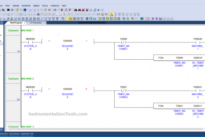
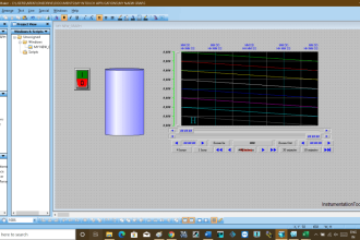
The below is the programming window of statement list (STL) where I have written the code of Always ON and OFF bit.
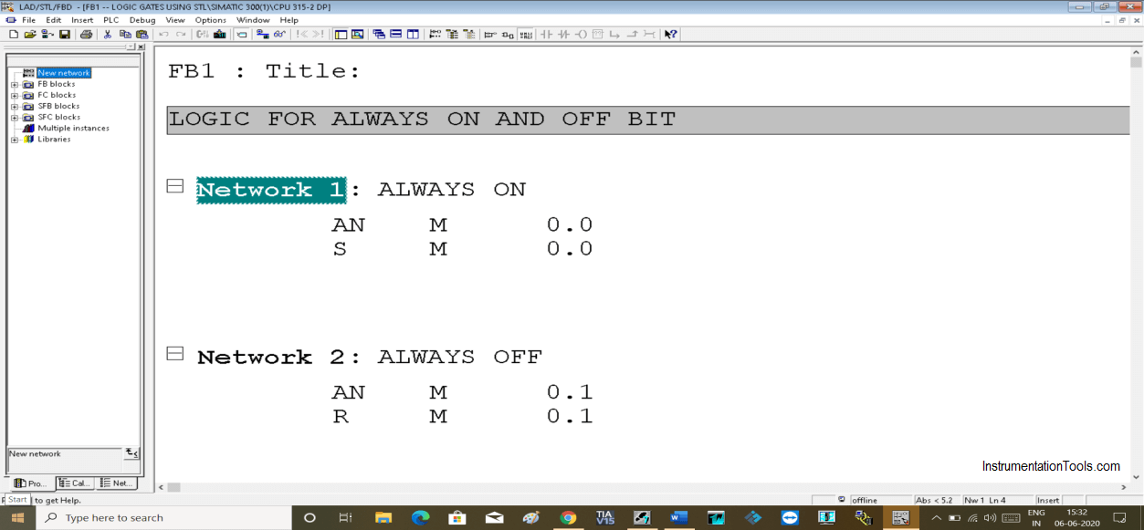
Logic for Always ON and Always OFF bit

Network 1:

I simply have used memory bit with AND NOT (AN) means NC contact in ladder logic.

In the second line of code, I have used “s” to set the same bit which I have used as input which allows this bit to remain always ON.

Network 2:

In this network, everything is the same except I want a bit to stay always OFF, I have used “R” means reset as an output coil.

Always ON and Always OFF bit using Ladder Logic

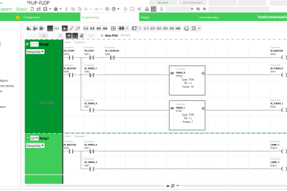
This is the window of ladder logic programming.
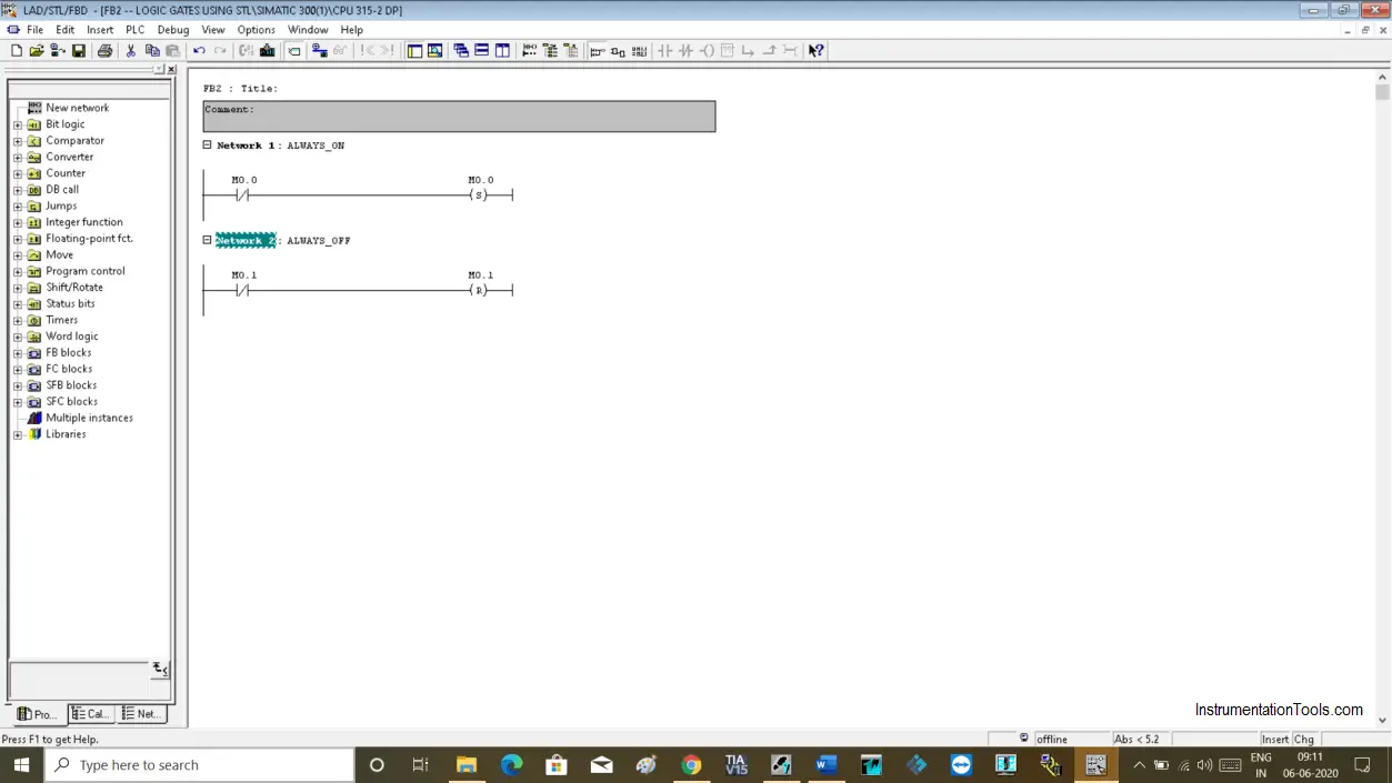
Bit always false in PLC

Network 1:

Here, in Network 1, I have used NC contact which always passes a signal, at output side set coil is used the same as input which makes it always true.

Network 2:

In network 2, I have used the Reset coil at the output side to make the bit always false.

Author: Suhel Patel

If you liked this article, then please subscribe to our YouTube Channel for PLC and SCADA video tutorials.

You can also follow us on Facebook and Twitter to receive daily updates.

Read Next:

  • Extended Timer Logic in PLC
  • Rewire Tool in Simatic Manager
  • STL to Find the Highest Value
  • History of Microprocessors
  • Motor Control Function Block
Don't Miss Our Updates
Be the first to get exclusive content straight to your email.
We promise not to spam you. You can unsubscribe at any time.
Invalid email address
You've successfully subscribed !

Continue Reading

Functions of SCADA
How to Retrieve PLC Project From Memory Card?
PLC Program for Daily Production Record
How to Operate a Group of Induction Motors using PLC Logic?
PLC Ladder Logic for Tanks Filling as per Priority
FIFO Instruction in Allen Bradley PLC Programming
Share This Article
Facebook Whatsapp Whatsapp LinkedIn Copy Link
Share
2 Comments
  • AndNi says:
    November 15, 2021 at 6:36 pm

    This is the right code…

    AN M 0.0
    S M 0.0

    A M 0.1
    R M 0.1

    Reply
  • Madhu says:
    November 24, 2022 at 6:25 am

    Nice Explination, I already subscribed your you tube channnel

    Reply

Leave a Reply Cancel reply

Your email address will not be published. Required fields are marked *

Stay Connected

128.3kFollowersLike
69.1kFollowersFollow
210kSubscribersSubscribe
38kFollowersFollow

Categories

Explore More

What is Relay Logic ?
Tank Filling and Emptying using Intouch Scada Script
How to Work with Delta PLC Simulator?
#18 PLC Best Practices – Store PLC Hard Stop Events from Faults
How to Interchange ON Delay Timer and OFF Delay Timer in a PLC
Types of Interlocks
PLC Mixing Process with Adjustable Timer and Valve Control
HMI Handbook

Keep Learning

One Shot Rising PLC Example Program

One Shot Rising PLC Example Program

What is RS Linx - Types of Softwares in Rockwell Automation

What is RS Linx? Types of Software in Rockwell Automation

User Defined Function Blocks in PLC

What are User Defined Function Blocks in PLC?

PLC Star-Delta starter with interlock

Schneider PLC Example Program for Star-Delta System

What is Fail-safe in Siemens PLC?

What is Fail-safe in Siemens PLC?

Conditional Jump instruction

Jump Instruction in Siemens Tia Portal

Masked Move Instructions

How to use Masked Move Instruction in PLC

two-way communication between PLC systems

Transferring Data Across PLC Systems – TSEND_C and TRCV_C

Learn More

PLC Lamp Control using Logic Condition

Lamp Control using PLC Logic Condition

Concept of DCS in Industrial Automation

Concept of DCS in Industrial Automation

Disadvantages of Resistance Temperature Detectors (RTD)

Disadvantages of Resistance Temperature Detectors

Solenoid Valve Terminology

Solenoid Valves Terminology

PLC Pump Control

PLC Pump Control: 10 seconds ON & 20 seconds OFF

What is a Differential Mode Signal

Difference Between Differential Mode and Common Mode

Non‐contact RADAR Level Transmitter Pulse

Non Contact RADAR Level Transmitter Principle, Limitations, Design, Installation and Calibration

Difference Between LED and LDR

Difference Between LED and LDR

Menu

  • About
  • Privacy Policy
  • Copyright

Quick Links

  • Learn PLC
  • Helping Hand
  • Part Time Job

YouTube Subscribe

Follow US
All rights reserved. Reproduction in whole or in part without written permission is prohibited.
Welcome Back!

Sign in to your account

Username or Email Address
Password

Lost your password?