Inst ToolsInst ToolsInst Tools
  • Courses
  • Automation
    • PLC
    • Control System
    • Safety System
    • Communication
    • Fire & Gas System
  • Instrumentation
    • Design
    • Pressure
    • Temperature
    • Flow
    • Level
    • Vibration
    • Analyzer
    • Control Valve
    • Switch
    • Calibration
    • Erection & Commissioning
  • Interview
    • Instrumentation
    • Electrical
    • Electronics
    • Practical
  • Q&A
    • Instrumentation
    • Control System
    • Electrical
    • Electronics
    • Analog Electronics
    • Digital Electronics
    • Power Electronics
    • Microprocessor
  • Request
Search
  • Books
  • Software
  • Projects
  • Process
  • Tools
  • Basics
  • Formula
  • Power Plant
  • Root Cause Analysis
  • Electrical Basics
  • Animation
  • Standards
  • 4-20 mA Course
  • Siemens PLC Course
Reading: Power Triangle
Share
Notification Show More
Font ResizerAa
Inst ToolsInst Tools
Font ResizerAa
  • Courses
  • Design
  • PLC
  • Interview
  • Control System
Search
  • Courses
  • Automation
    • PLC
    • Control System
    • Safety System
    • Communication
    • Fire & Gas System
  • Instrumentation
    • Design
    • Pressure
    • Temperature
    • Flow
    • Level
    • Vibration
    • Analyzer
    • Control Valve
    • Switch
    • Calibration
    • Erection & Commissioning
  • Interview
    • Instrumentation
    • Electrical
    • Electronics
    • Practical
  • Q&A
    • Instrumentation
    • Control System
    • Electrical
    • Electronics
    • Analog Electronics
    • Digital Electronics
    • Power Electronics
    • Microprocessor
  • Request
Follow US
All rights reserved. Reproduction in whole or in part without written permission is prohibited.
Inst Tools > Blog > Electrical Theory > Power Triangle

Power Triangle

Last updated: August 1, 2018 2:22 am
Editorial Staff
Electrical Theory
No Comments
Share
1 Min Read
SHARE

In AC circuits, current and voltage are normally out of phase and, as a result, not all the power produced by the generator can be used to accomplish work. By the same token, power cannot be calculated in AC circuits in the same manner as in DC circuits.

The power triangle, shown in Figure 1, equates AC power to DC power by showing the relationship between generator output (apparent power – S) in volt-amperes (VA), usable power (true power – P) in watts, and wasted or stored power (reactive power – Q) in volt-amperes-reactive (VAR).

The phase angle (θ) represents the inefficiency of the AC circuit and corresponds to the total reactive impedance (Z) to the current flow in the circuit.

Power Triangle

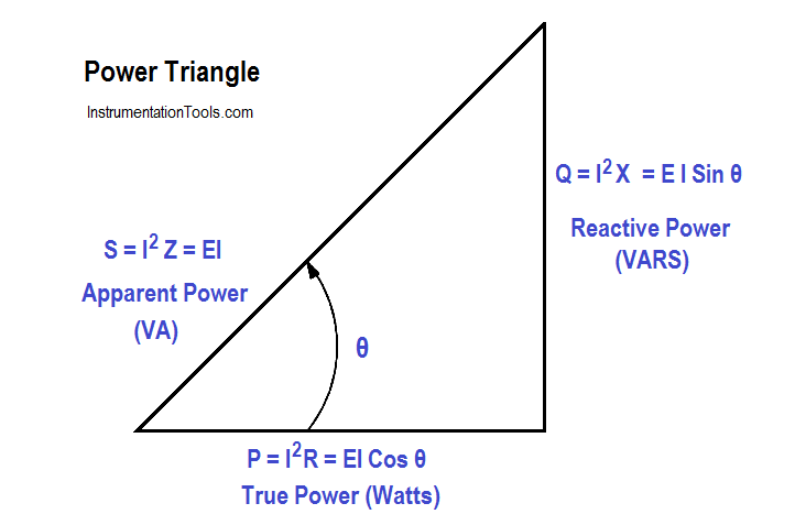
Figure 1 : Power Triangle

The power triangle represents comparable values that can be used directly to find the efficiency level of generated power to usable power, which is expressed as the power factor (discussed later). Apparent power, reactive power, and true power can be calculated by using the DC equivalent (RMS value) of the AC voltage and current components along with the power factor.

Don't Miss Our Updates
Be the first to get exclusive content straight to your email.
We promise not to spam you. You can unsubscribe at any time.
Invalid email address
You've successfully subscribed !

Continue Reading

DC Generator
Inductive Time Constant
Types of Batteries
AC Induction Motor Slip
Transformer Voltage Ratio
Series Open Circuit Faults
Share This Article
Facebook Whatsapp Whatsapp LinkedIn Copy Link
Share
Leave a Comment

Leave a Reply Cancel reply

Your email address will not be published. Required fields are marked *

Stay Connected

128.3kFollowersLike
69.1kFollowersFollow
210kSubscribersSubscribe
38kFollowersFollow

Categories

Explore More

Magnetic Circuits
Electrical System Components and Protection Devices
Kirchhoff’s Laws
DC Machines Construction
Voltage Divider
Moving Iron Vane Meter Movement
What is Synchroscope ?
Parallel AC Generators

Keep Learning

Center Tap Full-Wave Rectifier

Full-Wave Rectifier Circuit

Unbalanced 3 Phase Loads

Unbalanced 3 Phase Loads

Synchronous Motor Principle

Synchronous Motors

Shunt-Wound DC Motor

Shunt-Wound Motor Operation

Phase angle

AC Generation Analysis : Effective Values, Phase Angle and Frequency

relationship between resistance, reactance, and impedance

Impedance

Electric Short Circuit

Series Short Circuit Faults

Battery Interview QuBattery Interview Question and Answersestion and Answers

Battery Terminology

Learn More

Fieldbus Flow Transmitter Calibration

Foundation Fieldbus Transmitter Calibration

PLC Programming in Hindi - Siemens Tia Portal Full Course

PLC Programming in Hindi – Siemens Tia Portal Full Course Free

Mixing Tank Relay Circuit

PLC Program for Mixing Tank

Lamp Counter Logic

Function Block (FB) for Motor Control Logic

Specific-Conductance-Calibration-Procedure

Types of AC Motors and DC Motors

Hook-up Diagram for Pressure Gauge

What is Instrument Hook Up Diagram ?

Fieldbus Interview Questions

Interview Questions on Fieldbus Communication

Parking Lights PLC Program Explained with Video

Parking Lights PLC Program Explained with Video

Menu

  • About
  • Privacy Policy
  • Copyright

Quick Links

  • Learn PLC
  • Helping Hand
  • Part Time Job

YouTube Subscribe

Follow US
All rights reserved. Reproduction in whole or in part without written permission is prohibited.
Welcome Back!

Sign in to your account

Username or Email Address
Password

Lost your password?