You are supplying or buying an industrial automation system and one of the most important documents in them is system architecture.
Industrial automation is a vast system of PLC, IO modules, SCADA, HMI, and networks. If you do not know which component to whom and why is the linking done between them, then you will not be able to get the network as well as data flow between them.
So, it is important to draw an architectural design of the whole system. In this post, we will see how to design a system architecture in industrial automation.
What is system architecture?
System architecture is a design that depicts which components are used in the automation system and how they are interconnected. It does not show electrical panel components.
Basically, the main role is to show major devices like PLC, SCADA, HMI, IO modules, network switches, VFD, or another type of device that has communication protocol in it and is connected to the PLC system too.
System architecture thus helps the engineer to understand the flow of the system design. If you can identify that a PLC port cable is connected to some other device that is wrong, then you can rectify the fault by interchanging the wire or changing the device itself. So, this drawing must be properly made with correct information, because it serves as the base for troubleshooting, design, and maintenance.
A system architecture should show the mentioned components with their quantities on the other side of the page (we will see it later in the post). The components should be linked by the corresponding communication protocols, thus determining the placement and data flow of the network.
Design of system architecture
Refer to the below image. You can see how the components are linked to each other and also described with their quantities and model numbers.
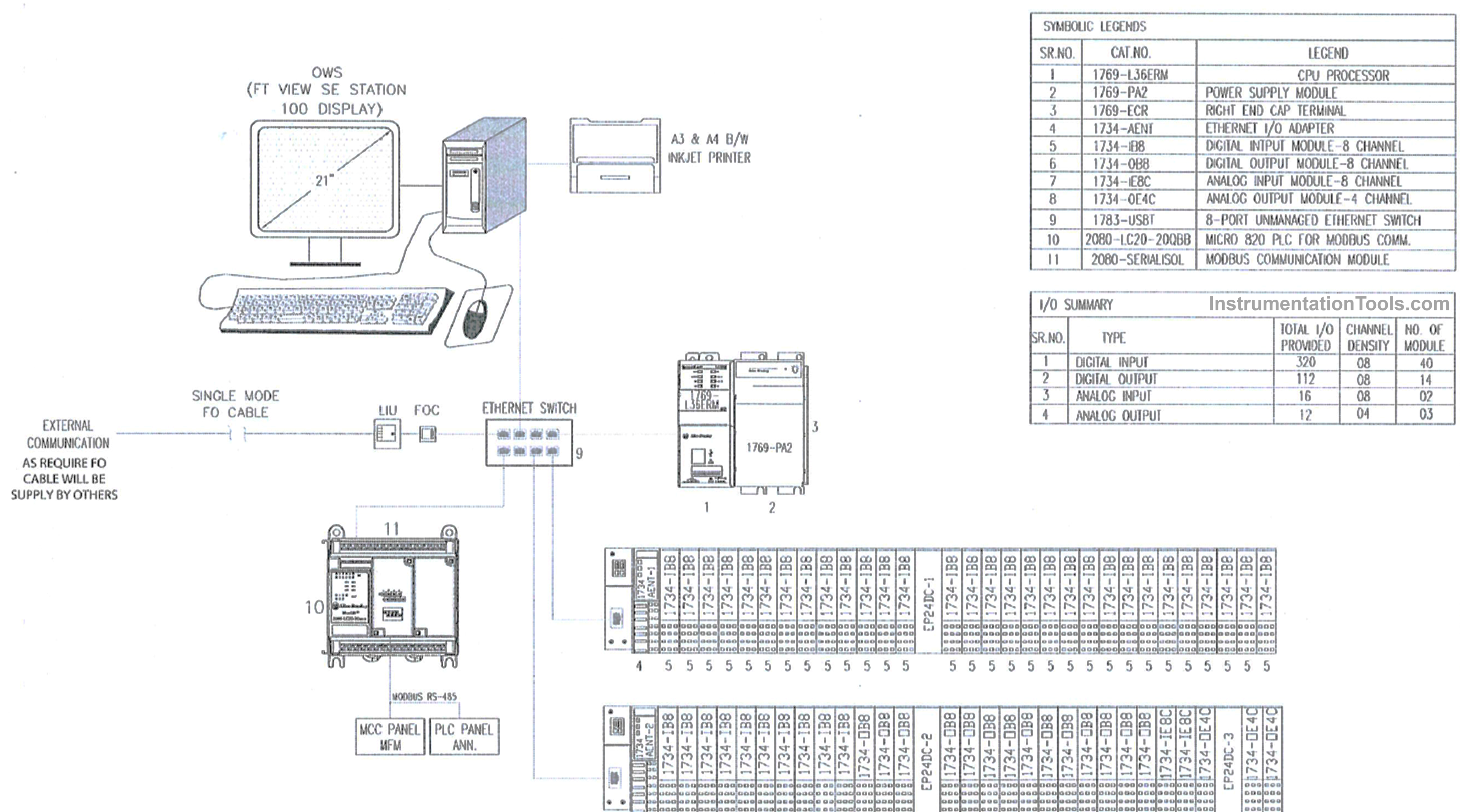
Let us consider the things below when designing a system architecture:
From the automation requirements, you need to list out the types of devices like PLC, PC, HMI, VFD, and any other device having a communication port, network switches, and IO module.
Then, in the right-hand side corner of a page (or any free space according to your convenience), write down all these quantities with their exact model numbers. In the special case of PLC, also mention the exact number of IO counts separately (digital inputs, digital outputs, analog inputs, and analog outputs) for easy troubleshooting and diagnostics.
Now, you must highlight the communication ports in each of the devices. This enables you to make decisions on which port will be kept spare or which port will be designated for a specific purpose.
Before making any network topology, you must first know which type of network the PLC and its module support. Without that, you cannot just randomly create any design. Actually speaking, the role of each device is pre-decided during the proposal stage. So you must know the role of each device and its network port, thus helping in designing the correct topology like line, star, bus, mesh, or any other.
Now, start placing the components starting from PLC. In the PLC, there can be expansion modules plugged in or connected via the network. Be it any, you need to draw every module with proper labels. Also, the PLC name must be properly mentioned. Once drawn, you need to link them by lines, showing which component is connected to what. For this, you need to know the configuration of the communication port.
Once done, start with graphic displays like HMI or SCADA PC. In a small system with no network switch, the PLC is drawn directly with a PC or HMI connection. In larger systems, switches come into role, and you must appropriately draw the line from the respective components.
Apart from Ethernet, which is the most generally used network protocol, other ones too like Modbus, CAN Open, or something like that are used in a system. For example, if you have an energy meter that has an RS485 port in it and you want to integrate it with PLC, then draw a line between both serial ports. In the image above, you can also draw arrows indicating where the communication line is going, instead of joining the points all the way.
If any port in any component is not used, mention it as spare. This helps to determine the future use of the network.
The whole idea is that if you are clear with your application needs, then only you can design a proper system architecture with ease. All required is proper labeling, communication protocol knowledge, and redundancy knowledge.
In this way, we saw how to design a system architecture in industrial automation.
Read Next:
- Process Control Systems Basic Concept
- Process Control Systems Philosophy Document
- System architecture and process control Design
- 30 concerns for control systems Design Basis
- Instrumentation Design Engineer Responsibilities
![Multi-Tank Liquid Level Control System with Fill Priority [PLC]](https://instrumentationtools.com/wp-content/uploads/2025/07/Multi-Tank-Liquid-Level-Control-System-with-Fill-Priority-PLC-420x280.jpg)