Create a PLC program for auto and manual liquid tank system using EcoStruxure Machine Expert-Basic by Schneider Electric.
PLC Program for Liquid Tank
This article discusses the PLC program for Filling And Emptying tank liquids which can be RUN automatically or manually. When the system is manually operated, the operation of the Liquid Pump, Input Valve, and Output Valve can only be controlled using the Push Button.
When the system runs automatically, if the liquid Tank is empty, the input valve will automatically Open and the liquid pump will Activate 5 seconds later. During the liquid filling process, the Output Valve will always be Closed.
When the liquid Tank is full, the pump input valve will Close and the liquid pump will be Disabled, and the output valve will Open. The liquid pump and input valve will be Active again when the liquid Tank is empty.
Program Explained
In this program, the system will only RUN if the START_SYSTEM (I0.0) button is pressed and will only STOP if the STOP_SYSTEM (I0.1) button is pressed. By default, the system is in Manual Mode. If the MODE button (I0.2) is pressed then the system Mode will change to Automatic.
In Manual Mode, the PB_PUMP (I0.7) button activates the PUMP Output (Q0.0), the PB_VALVE_IN (I0.5) button activates the VALVE_IN Output (Q0.1), and the PB_VALVE_OUT (I0.6) button activates Output VALVE_OUT (Q0.2).
In Automatic Mode, the system will RUN when the MODE button (I0.2) becomes HIGH/True. In Automatic Mode, the system does not use push buttons to control the PUMP Output (Q0.0), VALVE_IN Output (Q0.1), and VALVE_Out Output (Q0.2). In Automatic Mode, SENS_LOW (I0.3) is used to indicate the lowest point of liquid in the Tank (low level), and SENS_HIGH (I0.4) is used to indicate the highest point of liquid in the Tank (high level).
When the liquid Tank is empty, the NC (Normally Close) SENS_LOW (I0.3) and SENS_HIGH (I0.4) contacts will Activate VALVE_IN (Q0.1) and the PUMP Output (Q0.0) will Activate 5 seconds later to RUN the liquid filling process.
When the Tank is full then the Contact NO (Normally Close) of SENS_LOW (I0.3) and SENS_HIGH (I0.4) will Activate the output VALVE_OUT (Q0.2) to RUN the process of emptying the liquid. VALVE_OUT (Q0.2) will be Closed when the NO (Normally open) contacts of SENS_LOW (I0.3) and SENS_HIGH (I0.4) are LOW/False.
I/O Details
Addressing Input, Output, TIM, Bit Memory, and Word Memory details as follows.
| Comment | Input (I) | Output(Q) | Memory Bits |
| START_SYSTEM | I0.0 | ||
| STOP_SYSTEM | I0.1 | ||
| MODE | I0.2 | ||
| SENS_LOW | I0.3 | ||
| SENS_HIGH | I0.4 | ||
| PB_VALVE_IN | I0.5 | ||
| PB_VALVE_OUT | I0.6 | ||
| PB_PUMP | I0.7 | ||
| PUMP | Q0.0 | ||
| VALVE_IN | Q0.1 | ||
| VALVE_OUT | Q0.2 | ||
| SYSTEM_ON | M0 | ||
| PUMP_1 | M1 | ||
| VALVE_IN_1 | M2 | ||
| VALVE_OUT_1 | M3 | ||
| PUMP_2 | M4 | ||
| VALVE_IN_2 | M5 | ||
| VALVE_OUT_2 | M6 |
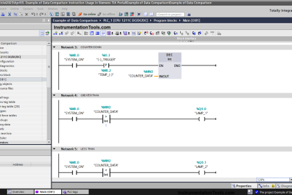
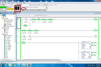
PLC Programming Code
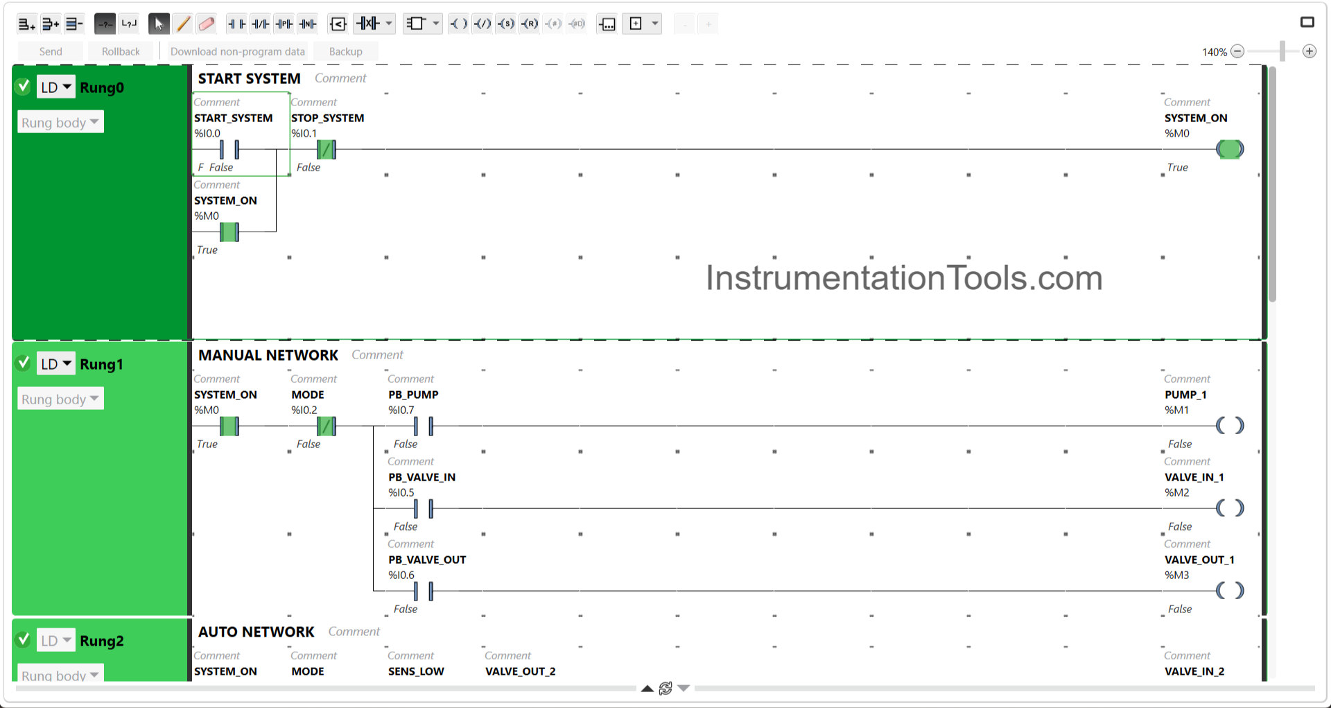
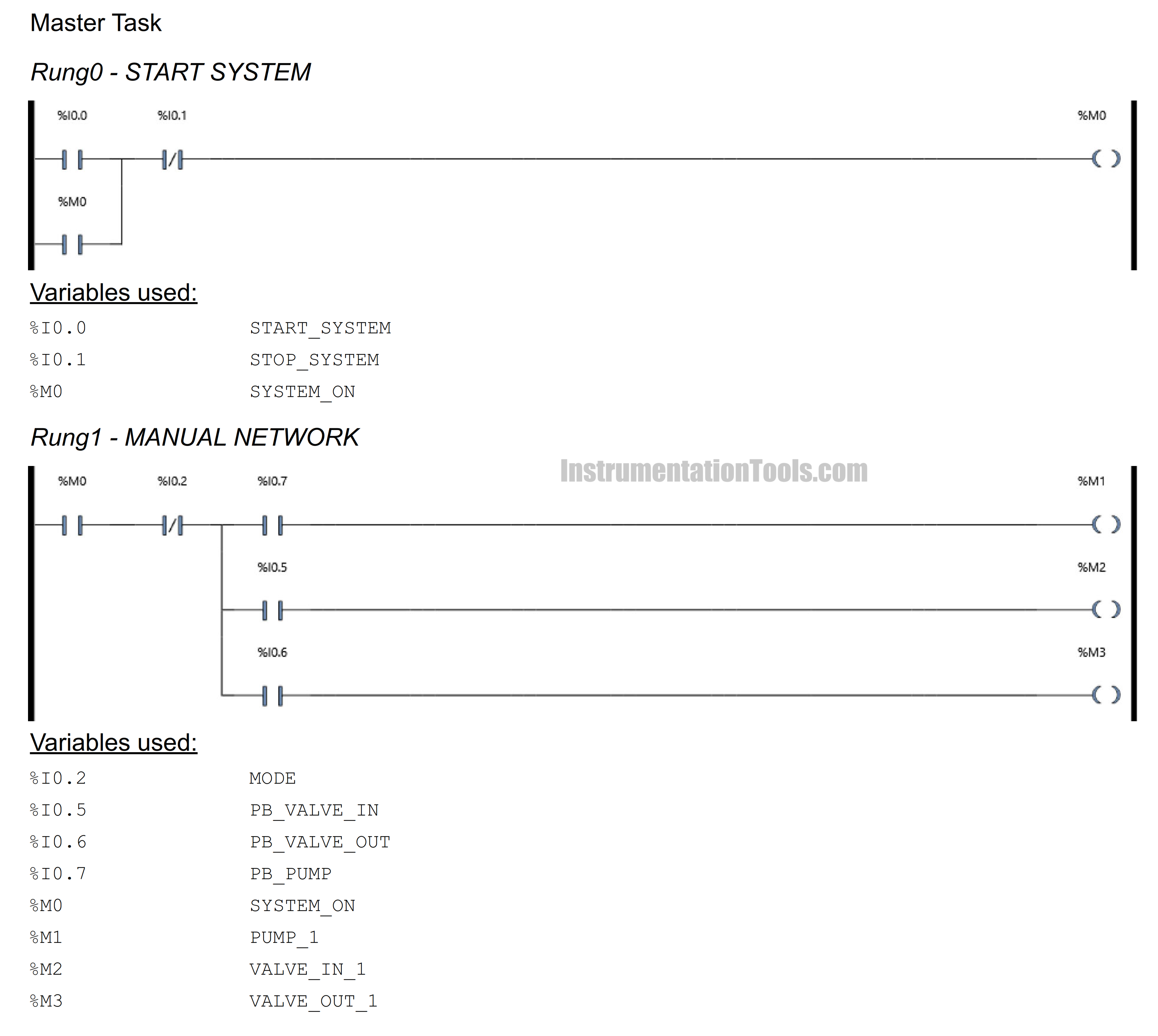
The image above shows when the memory Output bit SYSTEM_ON (M0) has been Active. Once the START_SYSTEM (I0.0) push button is pressed then the memory Output bit SYSTEM_ON (M0) becomes Active. Due to the latching, the memory output bit SYSTEM_ON (M0) remains Active even though the START_SYSTEM (I0.0) push button is released.
In Rung-1, (MANUAL NETWORK) you can see that the system can RUN because of the NC (Normally Close) contact from MODE (I0.2).

The image above shows the condition of the output memory bits PUMP_1 (M1), VALVE_IN_1 (M2), and VALVE_OUT_1 (M3) which have been activated manually.
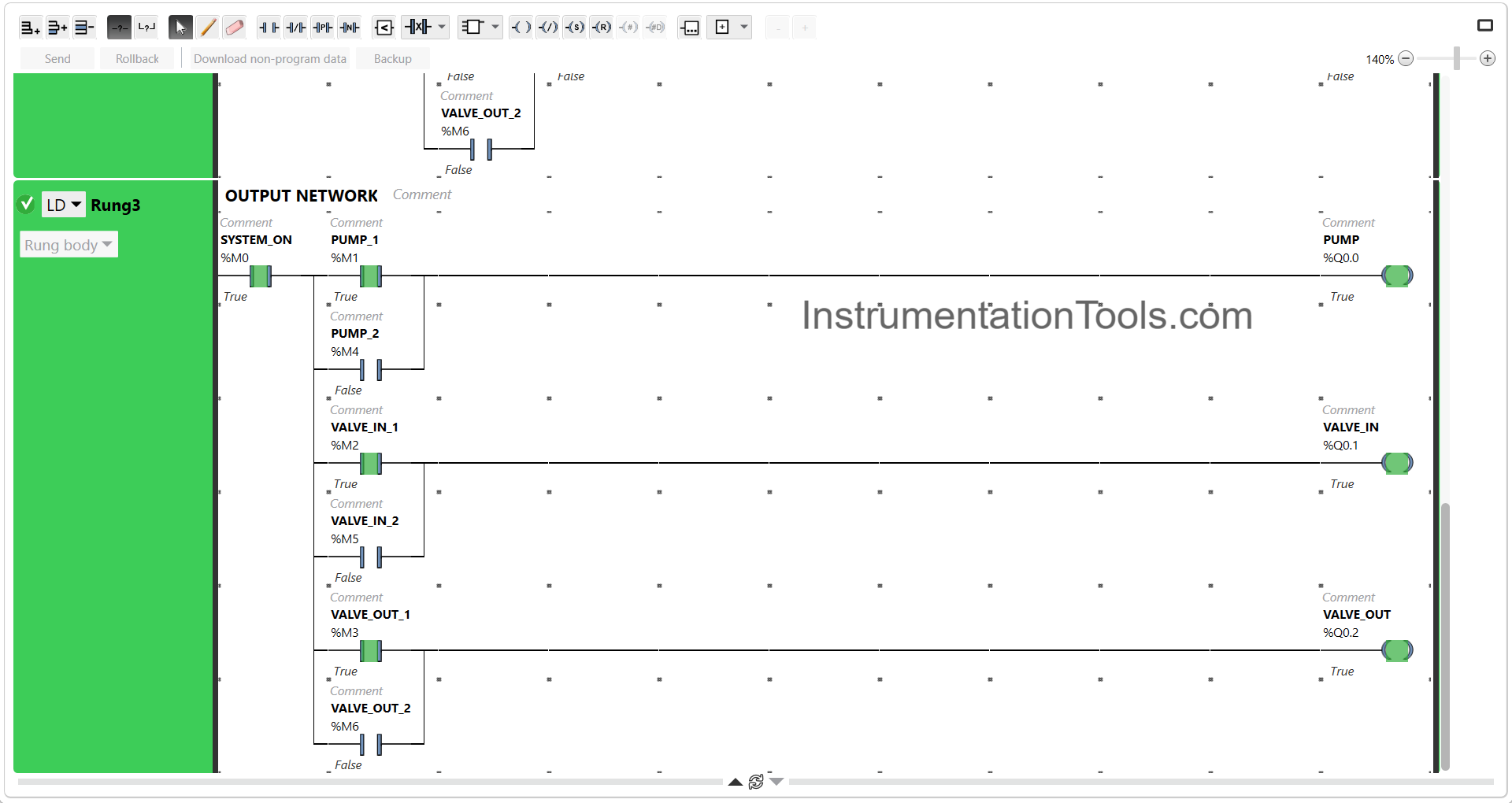
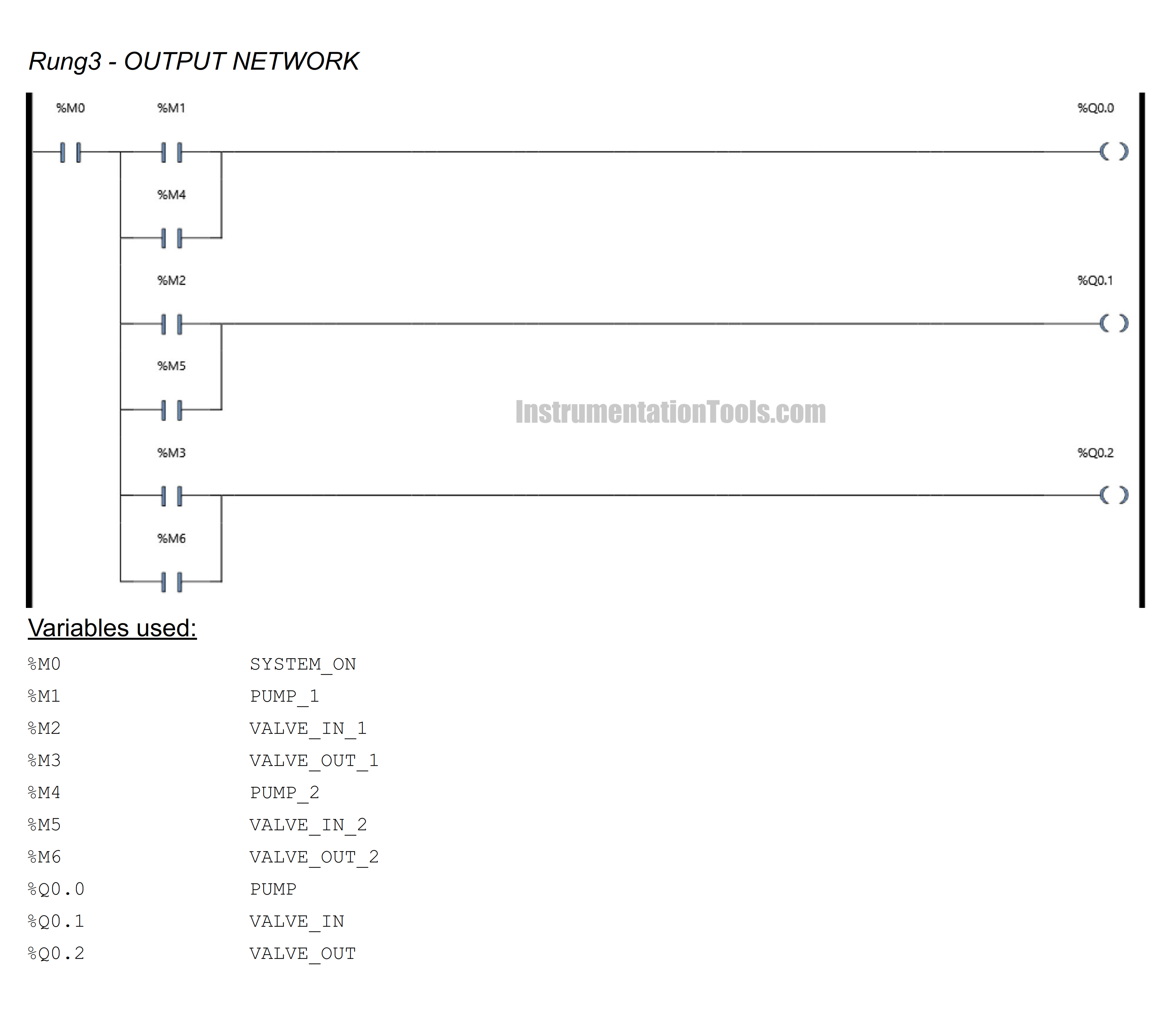
The picture above shows the Output PUMP (Q0.0), VALVE_IN (Q0.1), and VALVE_OUT (Q0.2) which have been Active because the NO (Normally Open) contacts of the memory bits PUMP_1 (M1), VALVE_IN_1 (M2), VALVE_OUT_1 (M3) are in HIGH/True condition.
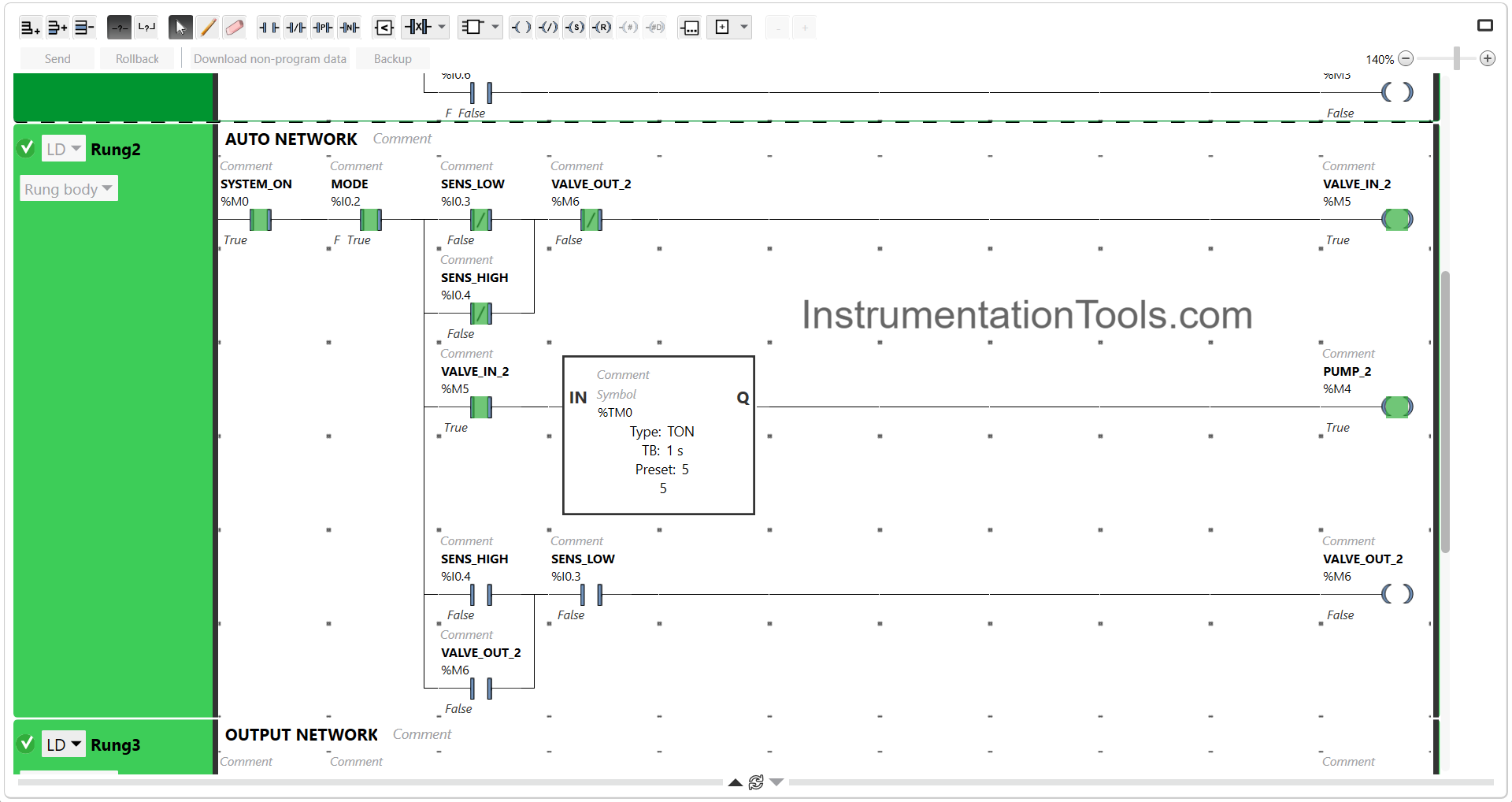
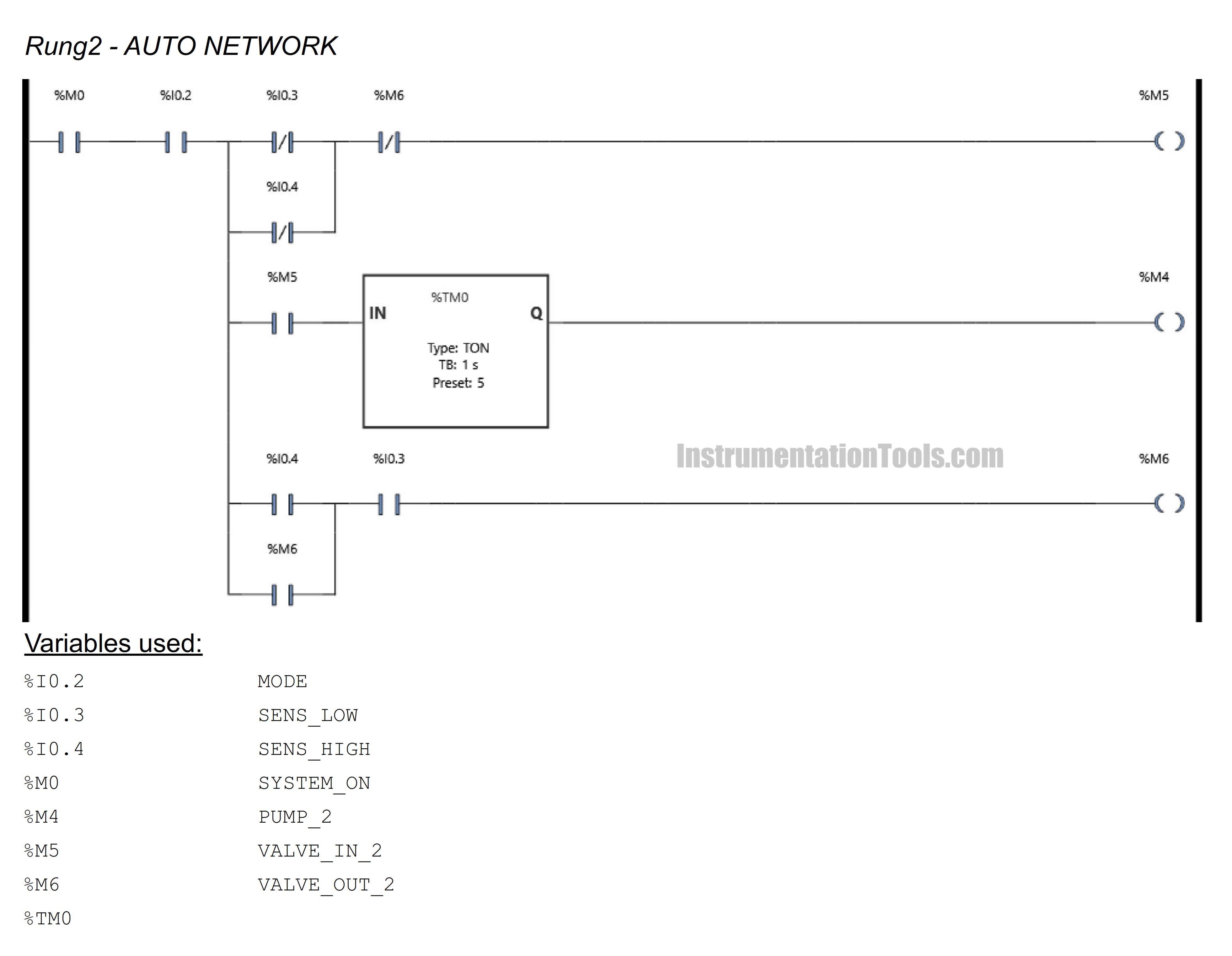
The figure above shows the condition when the system has been RUN in automatic Mode. Because the liquid Tank is empty, the memory Output bit VALVE_IN_2 (M5) becomes Active.
Because the system has been running for more than 5 seconds then the memory Output bit PUMP_2 (M4) becomes Active.
This Step has been going on the process of filling the liquid in the Tank.
Because the NO (Normally Open) contacts of the VALVE_IN_2 (M5) and PUMP_2 (M4) bit memory are Active, the pump (Q0.0) and VALVE_IN (Q0.1) outputs are Active.
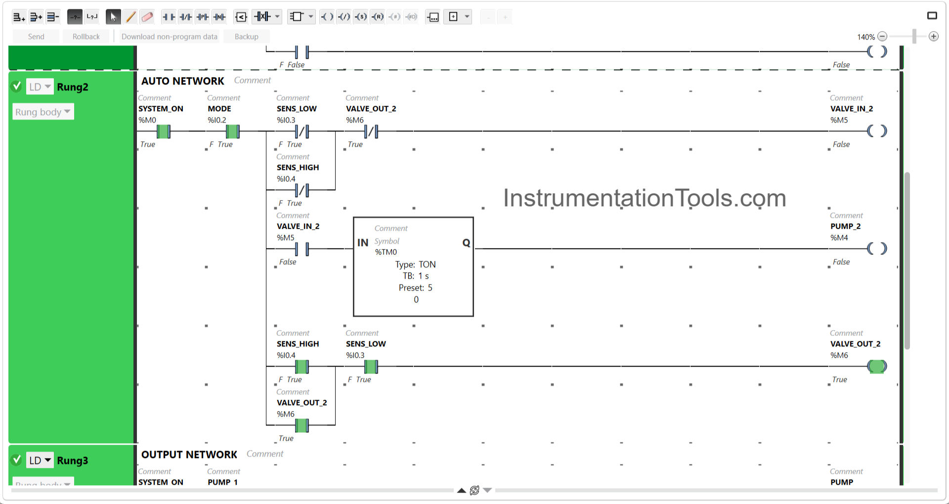
The picture above shows the process of emptying the liquid tank. Because the tank is full, the memory Output bit VALVE_OUT_2 (M6) becomes Active. The Interlock function of the VALVE_OUT_2 (M6) bit memory makes the VALVE_IN_2 (M5) and PUMP_2 (M4) bit memory outputs Disabled.
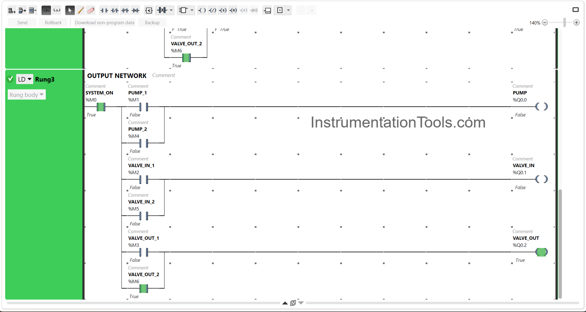
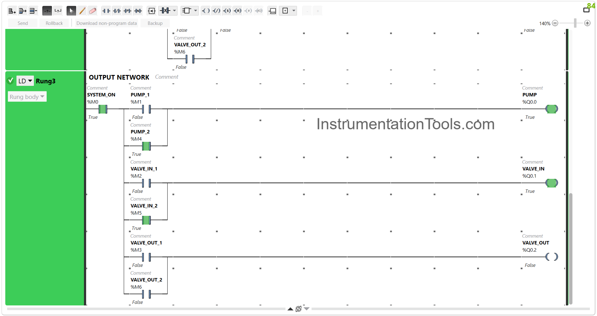
Because the NO (Normally Open) contact of VALVE_OUT_2 (M6) has been Active, the Output of VALVE_OUT (Q0.2) becomes Active.
If you liked this article, please subscribe to our YouTube Channel for PLC and SCADA video tutorials.
You can also follow us on Facebook and Twitter to receive daily updates.
Read Next:
- Batch Mixing with PLC Ladder Logic Program
- Ecostruxure Machine Expert HVAC Software
- Tank Filling and Emptying using Scada Script
- PLC Program for Water Level Control Logic
- Automatic Empty Bottle detection using PLC