Inst ToolsInst ToolsInst Tools
  • Courses
  • Automation
    • PLC
    • Control System
    • Safety System
    • Communication
    • Fire & Gas System
  • Instrumentation
    • Design
    • Pressure
    • Temperature
    • Flow
    • Level
    • Vibration
    • Analyzer
    • Control Valve
    • Switch
    • Calibration
    • Erection & Commissioning
  • Interview
    • Instrumentation
    • Electrical
    • Electronics
    • Practical
  • Q&A
    • Instrumentation
    • Control System
    • Electrical
    • Electronics
    • Analog Electronics
    • Digital Electronics
    • Power Electronics
    • Microprocessor
Search
  • Books
  • Software
  • Projects
  • Process
  • Tools
  • Basics
  • Formula
  • Power Plant
  • Root Cause Analysis
  • Electrical Basics
  • Animation
  • Standards
  • 4-20 mA Course
  • Siemens PLC Course
Reading: PLC Example to Control LEDs Via Switches
Share
Notification Show More
Font ResizerAa
Inst ToolsInst Tools
Font ResizerAa
  • Courses
  • Design
  • PLC
  • Interview
  • Control System
Search
  • Courses
  • Automation
    • PLC
    • Control System
    • Safety System
    • Communication
    • Fire & Gas System
  • Instrumentation
    • Design
    • Pressure
    • Temperature
    • Flow
    • Level
    • Vibration
    • Analyzer
    • Control Valve
    • Switch
    • Calibration
    • Erection & Commissioning
  • Interview
    • Instrumentation
    • Electrical
    • Electronics
    • Practical
  • Q&A
    • Instrumentation
    • Control System
    • Electrical
    • Electronics
    • Analog Electronics
    • Digital Electronics
    • Power Electronics
    • Microprocessor
Follow US
All rights reserved. Reproduction in whole or in part without written permission is prohibited.
Inst Tools > Blog > PLC Tutorials > PLC Example to Control LEDs Via Switches

PLC Example to Control LEDs Via Switches

In this article, you will learn the PLC example to control LEDs via switches and understand the ladder logic explanation.

Last updated: March 19, 2024 6:47 am
Editorial Staff
PLC Tutorials
No Comments
Share
5 Min Read
SHARE

In this article, you will learn the PLC example to control LEDs via switches and understand the ladder logic explanation.

Contents
PLC ExampleInputsOutputsLadder Diagram to Control LEDs Via SwitchesLadder Logic ExplanationWhen Any 1 Switch is ONWhen Any 2 Switches are ONWhen All 3 Switches are ONPLC Example Video

This PLC example is designed for engineering students to learn and practice the ladder logic. The implementation of the same PLC program for industrial usage will be different.

PLC Example

Design a PLC ladder logic for the following application.

We are using three switches to control three LED’s.

If any 1 Switch is ON, then LED I will be ON.

If any 2 Switches are ON, then LED II will be ON.

If all the 3 Switches are ON, then LED III will be ON.

In the previous article, we discussed the same PLC example using toggle switches, Learn the logic.

Inputs

The required digital inputs are listed below.

Switch 1: I0.0

Switch 2: I0.1

Switch 3: I0.2

Outputs

The required digital outputs are listed below.

Motor 1: Q0.0

Motor 2: Q0.1

Motor 3: Q0.2

Ladder Diagram to Control LEDs Via Switches
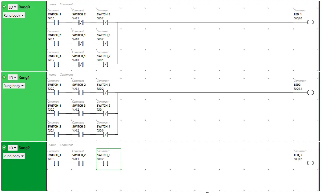
PLC Example to Control LEDs Via Switches

Ladder Logic Explanation

  • For this application, we have used EcoStruxure Machine Expert Basic v1.2 software for the PLC programming.
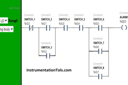
  • In the above program, we have used Normally Open Contacts as well as Normally Closed Contacts for Switch 1 (I0.0), Switch 2 (I0.1), and Switch 3 (I0.2)
  • In Rung0, when any 1 switch (Normally Copen Contact) is turned ON and the other 2 switches (Normally Closed Contacts) are OFF, then LED 1 will turn ON.
  • To turn ON LED 2 Rung1, any 2 switches that are as Normally Open Contacts should be ON and the other remaining 1 switch as Normally Closed Contact should be OFF.
  • For LED 3 to be ON, switch 1, switch 2 and switch 3 in Rung2 are connected in series, thus implementing AND logic gate.
  • LED 3 will TURN ON when all the three switches are turned ON.

When Any 1 Switch is ON
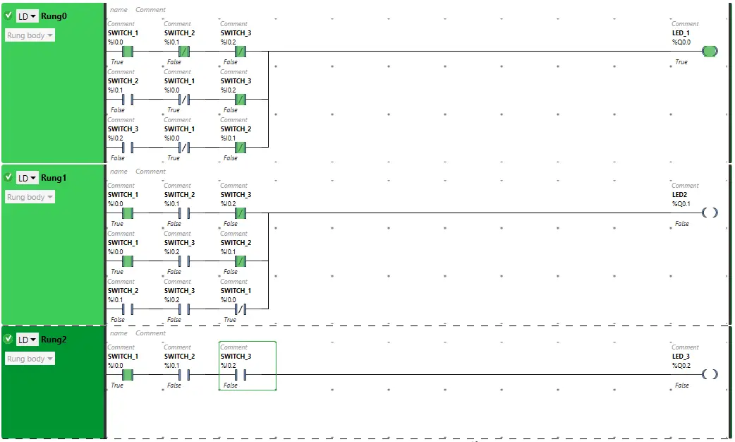
PLC Programming Example on LED Control Via Switches

The signal flows through switch 1 as it is in true state. In false state, switch 2 and switch 3 also pass signal to the outputs. Therefore, LED 1 will be ON.
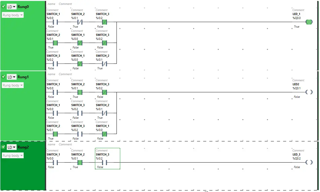
PLC LED Programming

LED I will TURN ON when switch 2 is turned ON and switch 1 and switch 3 are OFF as these are in normally closed contact state.
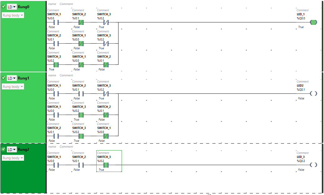
PLC Switches Programming

When switch 3 will be ON and other 2 switches which are normally closed contacts will be OFF, then LED 1 will turn ON.

Turning ON more than one switch will break the circuit. The Normally Closed Contact, when in true state, will not allow signal. As a result, LED 1 will be OFF.

When Any 2 Switches are ON
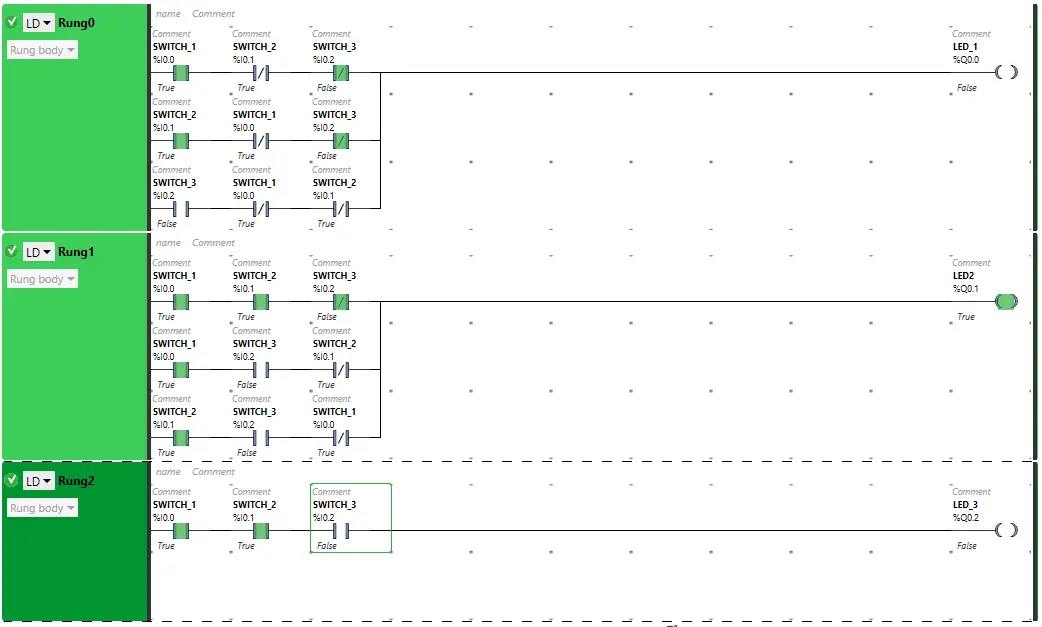
Switches Ladder Logic

LED 2 will TURN ON when switch 1, switch 2 are turned ON and Switch 3 is OFF. The switch 3 as Normally Closed Contact, in false state, will allow signal to pass through it.
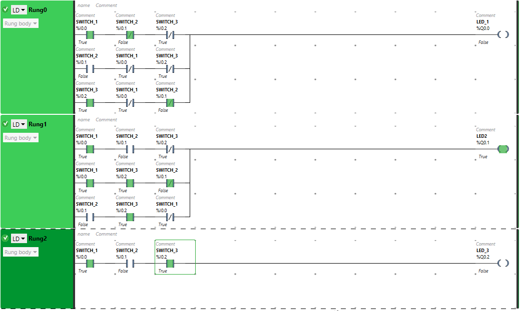
LEDs and Switches PLC Program

 When switch 1 and switch 3 are turned ON and switch 2 is OFF, LED 2 will turn ON. Switch 2 will allow signal when in false state.
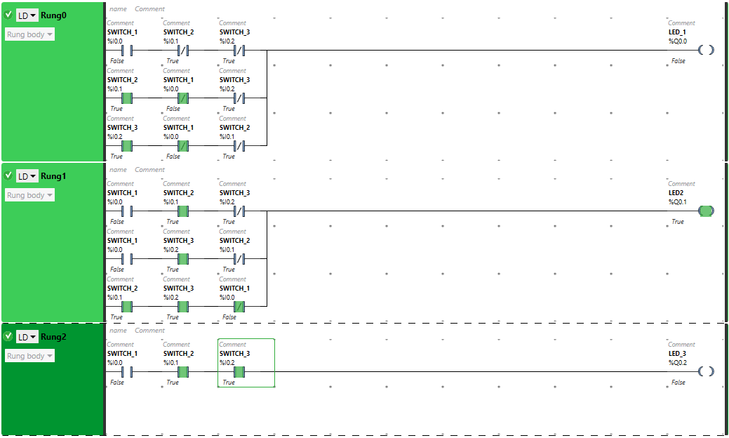
Switches Control PLC Logic

The signal flows through switch 2 and switch 3 as these are in true state. In false state, switch 1 also pass signal to the outputs. Therefore, LED 2 will be ON.

When more than two inputs are turned ON, the Normally Closed Contact used for the third switch will not close the circuit in true state. Therefore, the LED 2 will get OFF.

When All 3 Switches are ON
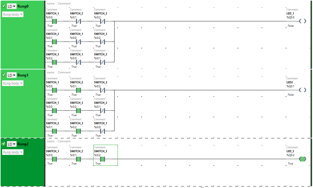
Ladder Diagram for Switches and Outputs

When all the three switches SWITCH 1 (I0.0), SWITCH 2 (I0.1), SWITCH 3 (I0.2) are turned ON, LED 3 will be ON and will turn OFF other Two outputs.

PLC Example Video

We explained this PLC example program in the below video. Watch and learn the ladder logic.

If you liked this article, then please subscribe to our YouTube Channel for PLC and SCADA video tutorials.

You can also follow us on Facebook and Twitter to receive daily updates.

Read Next:

  • Free Schneider PLC Training
  • Real-time PLC Automation Projects
  • How to Choose a PLC for a Project?
  • Moving Data between Siemens PLCs 
  • Siemens Communication using I-Device
Don't Miss Our Updates
Be the first to get exclusive content straight to your email.
We promise not to spam you. You can unsubscribe at any time.
Invalid email address
You've successfully subscribed !

Continue Reading

Difference Between PLCSIM and PLCSIM Advanced? – Siemens PLC
Write a PLC Program for Selector Machine using Structured Text
PLC Memory Organization – Data Files and Program Files
Upgrading and Migration of PLC Systems
Job Skills Required for Industrial Electrical Maintenance
The Purpose of Marshalling Cabinet or Marshalling Panel
Share This Article
Facebook Whatsapp Whatsapp LinkedIn Copy Link
Share
Leave a Comment

Leave a Reply Cancel reply

Your email address will not be published. Required fields are marked *

Stay Connected

128.3kFollowersLike
69.1kFollowersFollow
210kSubscribersSubscribe
38kFollowersFollow

Categories

Explore More

PLC Configuration of Profinet I/O System
How to Create New Project in Studio 5000?
Schneider Electric: Car Parking System with Calculations in PLC
Static and Temp Variables in PLC
PLC Instruction List for Motor Reverse and Forward Direction
Free Omron PLC Programming Course in HINDI
Function of Racks in PLC – Types of SIEMENS S7-400 PLC Racks
How to use Sub Routines with Allen Bradley PLC

Keep Learning

Wonderware Recipe Manager Plus

What is Recipe Management in SCADA?

SCADA Run

PLC Based Industrial Conveyor Ladder Logic

LCS Configuration equipped with LOTO Facility

Motor Control Signal Interface

Bottle’s Capping with Rotating Mechanism

PLC FBD Program for Bottle’s Capping with Rotating Mechanism

Simple Conveyor Control PLC Program

XG5000 Example of Simple Conveyor Control PLC Program

Count the Number of Cartons in a Storage Area PLC Logic

Count the Number of Cartons in a Storage Area PLC Logic

PLC Scan Time

PLC Scan Time

PLC Sizes and Applications

PLC Sizes and Applications

Learn More

Auto Transformer Schematic

Classification of Transformers

Absorption Chiller Principle - HVAC System

HVAC Double Effect Absorption Chiller

DP Transmitter Capillary arrangement

DP Transmitter Interface Level Measurement Principle, Limitations, Selection, Installation, Design & Calibration

Batteries MCQ - Multiple Choice Questions

Batteries MCQ – Multiple Choice Questions

PLC Commissioning and Testing

PLC Commissioning and Testing Procedure (Programmable Logic Controller)

Electric Short Circuit

Electric Circuit : Open & Short Circuits

Convert Linear mA to Square root mA

Convert Linear Percentage to Square root Percentage

Convert 2 wire RTD to 4 wire RTD Sensor

How to Convert 2 wire RTD into 3 or 4 wire RTD?

Menu

  • About
  • Privacy Policy
  • Copyright

Quick Links

  • Learn PLC
  • Helping Hand
  • Part Time Job

YouTube Subscribe

Follow US
All rights reserved. Reproduction in whole or in part without written permission is prohibited.
Welcome Back!

Sign in to your account

Username or Email Address
Password

Lost your password?