Inst ToolsInst ToolsInst Tools
  • Courses
  • Automation
    • PLC
    • Control System
    • Safety System
    • Communication
    • Fire & Gas System
  • Instrumentation
    • Design
    • Pressure
    • Temperature
    • Flow
    • Level
    • Vibration
    • Analyzer
    • Control Valve
    • Switch
    • Calibration
    • Erection & Commissioning
  • Interview
    • Instrumentation
    • Electrical
    • Electronics
    • Practical
  • Q&A
    • Instrumentation
    • Control System
    • Electrical
    • Electronics
    • Analog Electronics
    • Digital Electronics
    • Power Electronics
    • Microprocessor
  • Request
Search
  • Books
  • Software
  • Projects
  • Process
  • Tools
  • Basics
  • Formula
  • Power Plant
  • Root Cause Analysis
  • Electrical Basics
  • Animation
  • Standards
  • 4-20 mA Course
  • Siemens PLC Course
Reading: Methods of Transistor Biasing
Share
Font ResizerAa
Inst ToolsInst Tools
Font ResizerAa
  • Courses
  • Design
  • PLC
  • Interview
  • Control System
Search
  • Courses
  • Automation
    • PLC
    • Control System
    • Safety System
    • Communication
    • Fire & Gas System
  • Instrumentation
    • Design
    • Pressure
    • Temperature
    • Flow
    • Level
    • Vibration
    • Analyzer
    • Control Valve
    • Switch
    • Calibration
    • Erection & Commissioning
  • Interview
    • Instrumentation
    • Electrical
    • Electronics
    • Practical
  • Q&A
    • Instrumentation
    • Control System
    • Electrical
    • Electronics
    • Analog Electronics
    • Digital Electronics
    • Power Electronics
    • Microprocessor
  • Request
Follow US
All rights reserved. Reproduction in whole or in part without written permission is prohibited.
Inst Tools > Blog > Electronic Devices & Circuits > Methods of Transistor Biasing

Methods of Transistor Biasing

Last updated: September 27, 2016 5:37 am
Editorial Staff
Electronic Devices & Circuits
1 Comment
Share
1 Min Read
SHARE

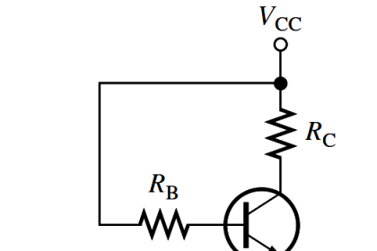
In the interest of simplicity and economy, it is desirable that transistor circuit should have a single source of supply—the one in the output circuit (i.e. VCC). The following are the most commonly used methods of obtaining transistor biasing from one source of supply (i.e. VCC ) :

(i) Base resistor method

(ii) Emitter bias method

(iii) Biasing with collector-feedback resistor

(iv) Voltage-divider bias

In all these methods, the same basic principle is employed i.e. required value of base current (and hence IC) is obtained from VCC in the zero signal conditions. The value of collector load RC is selected keeping in view that VCE should not fall below 0.5 V for germanium transistors and 1 V for silicon transistors.

For example, if     = 100 and the zero signal collector current IC is to be set at 1mA, then IB is made equal to IC / = 1/100 = 10 µA. Thus, the biasing network should be so designed that a base current of 10 µA flows in the zero signal conditions.
Don't Miss Our Updates
Be the first to get exclusive content straight to your email.
We promise not to spam you. You can unsubscribe at any time.
Invalid email address
You've successfully subscribed !

Continue Reading

Seven Segment Display Working Principle
Diodes Voltage Tripler
What is a Memristor? Principle, Advantages, Applications
Applications of Photo diodes
Comparison of MOSFET and BJT
Different Types of Diodes
Share This Article
Facebook Whatsapp Whatsapp LinkedIn Copy Link
Share
1 Comment
  • Dr Chandrashekar says:
    December 16, 2022 at 8:15 am

    good

    Reply

Leave a Reply Cancel reply

Your email address will not be published. Required fields are marked *

Stay Connected

128.3kFollowersLike
69.1kFollowersFollow
210kSubscribersSubscribe
38kFollowersFollow

Categories

Explore More

Dependent Current Source
Summary Of Transistor Bias Circuits
Resistors Principle & Applications
Troubleshooting a Biased Transistor
Working of NPN Transistor
Light Emitting Diode Operation
Full Wave Voltage Doubler using Diodes
Transistor Collector Characteristic Curves

Keep Learning

Electron Gun of CRT

Electron Gun of Cathode Ray Tube

Transistor Emitter Feedback Bias

Transistor Emitter Feedback Bias

zener-diode-as-voltage-regulator

Operation of Zener Diode Voltage Regulator

Basic Transistor Amplifier Circuit Principle

Basic Transistor Amplifier Circuit Principle

Insulators, Conductors and Semiconductors

capacitor-filter

Capacitor Filter Working Principle

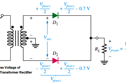
Peak Inverse Voltage of Center Tap Rectifier

Peak Inverse Voltage of Center Tap Rectifier

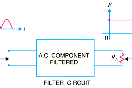
What is a Filter Circuit

What is a Filter Circuit ?

Learn More

HART Communication Tutorial 1

HART Communication Tutorial Part 4

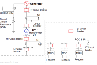
How to Read and Understand an Electrical Single Line Diagram?

How to Read and Understand an Electrical Single Line Diagram?

proximitor module

Bently Nevada Vibration System Verification Procedure

PLC Load Memory

What is Resources Tab in the Siemens PLC?

Chemical Sensors Objective Questions

Chemical Sensors Objective Questions

Automation in Mining Industry

Industrial Automation in the Mining Industry

Applications of Robots

Applications of Robots in Various Fields

SMART Transmitters Block Diagram

Smart Transmitters LRV & URV

Menu

  • About
  • Privacy Policy
  • Copyright

Quick Links

  • Learn PLC
  • Helping Hand
  • Part Time Job

YouTube Subscribe

Follow US
All rights reserved. Reproduction in whole or in part without written permission is prohibited.
Welcome Back!

Sign in to your account

Username or Email Address
Password

Lost your password?