In real-time for doing some work we require machines, tools, and equipment. For example, a hair dryer to dry the wet hair, an air conditioner to give the cool air, a washing machine to wash clothes, etc. In each of these, we have many components and parts. Each of the parts interacts with each other and gives us the desired results.
System
A system is a collection of many parts or subsystems that are integrated highly for producing an essential output. Every system takes some inputs, then manipulate, transforms, or processes them to give the desired output.
In short, a system is an arrangement or a combination of different physical components connected or related in such a manner as to form an entire unit to attain a certain objective.
Input
Input is the process or function of something put into a system or expended in its operation to achieve output or a result. The excitation applied to a control system from an external source in order to produce the output is known as input. Electricity and switches are inputs for a light, Petrol and Steering controls are inputs for car.
Output
The response obtained on the system is called output. The output depends on the input and the activity performed on the inputs by the system. For example, Glowing light and Motion of car are the outputs of the system.
Control
Control is the process of regulating the function or input for getting the desired results what we required. The process of regulating the inputs or directing the system so that desired objective is attained is called control. For example, adjustment of amplifier for getting the clear sound, regulating the fan speed for comfortable air.
Control System
For getting a specific output, the different physical elements are arranged and connected in such a manner to as to regulate, direct or command itself. The Control System is represented by a single block. Since the output is controlled by varying input, it is called as the control system. We will vary this input with some mechanism.
The major difference between system and control system is, in system we can get the normal output but in control system we can get the desired output by controlling the various parameters of the system.
Classification of Control System
Control systems are classified into two major categories.
They are:
- Open Loop Control System
- Closed Loop Control system
Open Loop Control System
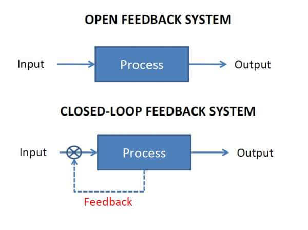
In an open loop control system, the output is not connected as feedback to the input. In this control system, the action is mainly independent of the desired output. A system in which the control action is totally independent of the output of the system is called as open-loop control system.
Examples of Open Loop Control Systems
Here are some examples of Open Loop Control Systems:
- Electric Hand Drier:
Hot output air comes out as long as you keep your hand under the machine irrespective of how much your hand is dried.
- Automatic Washing Machine:
This washing machine runs for the pre-set time irrespective of whether the washing process is complete or not
- Bread Toaster:
This toasting machine runs as per the defined time irrespective of whether toasting is completed or not
Advantages of Open Loop Control System
- Simple in construction and Time
- Less expensive
- Easy maintenance
- Stable operation
- Convenient to use
Disadvantages of Open Loop Control System
- Output may be inaccurate and it may change due to external and internal disturbances.
- Outputs are unreliable. The output is inconsistent over time.
- Any changes in output are not corrected automatically.
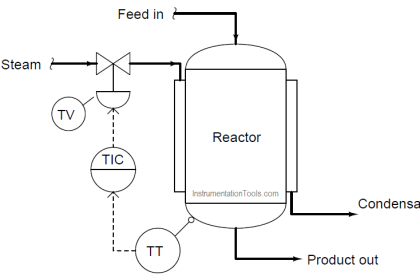
Closed Loop Control System
To achieve accurate results on the process, the output of the process needs to be monitored. If there is an error or an exact result is not obtained then the output is again fed back to the process for correcting the response through some parameters for getting the desired process.
The quantity of the output fed back to the system is called a “feedback signal” and the type of control system which uses feedback signals are called Closed Loop Control System. Feedback means that some portion of the output is returned back to the process to form a part of the system.
Closed loop systems are designed to automatically achieve and maintain the exact output condition by comparing it with the actual condition. This is done by the error signal, which creates the difference between the output and the reference input. It is a fully automatic control system in which its control action is dependent on the output.
Block Diagram:
Examples of Closed Loop Control Systems
Here are some examples of closed-loop in real life.
- Automatic Electric Iron:
Heating elements are controlled by the output temperature of the iron. The sensor reads the output temperature and compares it with the desired temperature. The error signal is generated with the help of desired temperature and output temperature. Then the error signal is given to the timer of the control system. This timer module will make the system on-off time of the heating element.
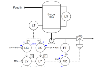
- Water Level Controller:
Input water is controlled by the water level in the tank. A sensor is used to measure the level of water in the tank. The sensor gives the output in the form of voltage level which is proportional to the water level. Depending on the signal the solenoid valve will get open or close and does the required process in the system.
- An Air Conditioner:
An air conditioner functions depending on the temperature of the room. The sensor in the conditioner checks the temperature of the room and generates an error signal by comparing it with the reference temperature. The error signal is read by the controller to switch on/off the air conditioner accordingly.
Advantages of Closed Loop Control System
- It is more accurate even in the presence of non-linearity.
- Highly accurate as any error arising is corrected due to the presence of feedback signal
- It facilitates automation.
- The closed-loop control system is less affected by noise.
- Very less response time and quick decision-making.
Disadvantages of Closed Loop Control System
- They are costlier.
- Complicated Design.
- Required more maintenance
- More care is needed to design a stable closed-loop system.
If you liked this article, then please subscribe to our YouTube Channel for Instrumentation, Electrical, PLC, and SCADA video tutorials.
You can also follow us on Facebook and Twitter to receive daily updates.
Read Next:
- Induction Motor using PLC Logic
- Offline and Online UPS Systems
- Modbus Driver for SCADA System
- Comparison of PNP and NPN Sensors
- Allen Bradley ControlLogix Architecture