Inst ToolsInst ToolsInst Tools
  • Courses
  • Automation
    • PLC
    • Control System
    • Safety System
    • Communication
    • Fire & Gas System
  • Instrumentation
    • Design
    • Pressure
    • Temperature
    • Flow
    • Level
    • Vibration
    • Analyzer
    • Control Valve
    • Switch
    • Calibration
    • Erection & Commissioning
  • Interview
    • Instrumentation
    • Electrical
    • Electronics
    • Practical
  • Q&A
    • Instrumentation
    • Control System
    • Electrical
    • Electronics
    • Analog Electronics
    • Digital Electronics
    • Power Electronics
    • Microprocessor
  • Request
Search
  • Books
  • Software
  • Projects
  • Process
  • Tools
  • Basics
  • Formula
  • Power Plant
  • Root Cause Analysis
  • Electrical Basics
  • Animation
  • Standards
  • 4-20 mA Course
  • Siemens PLC Course
Reading: Add On Instructions Programming – Analog Input Devices in Studio 5000
Share
Notification Show More
Font ResizerAa
Inst ToolsInst Tools
Font ResizerAa
  • Courses
  • Design
  • PLC
  • Interview
  • Control System
Search
  • Courses
  • Automation
    • PLC
    • Control System
    • Safety System
    • Communication
    • Fire & Gas System
  • Instrumentation
    • Design
    • Pressure
    • Temperature
    • Flow
    • Level
    • Vibration
    • Analyzer
    • Control Valve
    • Switch
    • Calibration
    • Erection & Commissioning
  • Interview
    • Instrumentation
    • Electrical
    • Electronics
    • Practical
  • Q&A
    • Instrumentation
    • Control System
    • Electrical
    • Electronics
    • Analog Electronics
    • Digital Electronics
    • Power Electronics
    • Microprocessor
  • Request
Follow US
All rights reserved. Reproduction in whole or in part without written permission is prohibited.
Inst Tools > Blog > Control Systems > Add On Instructions Programming – Analog Input Devices in Studio 5000

Add On Instructions Programming – Analog Input Devices in Studio 5000

In this article, you will learn how to configure analog input devices using Add-on instructions in studio 5000 Rockwell software.

Last updated: July 3, 2022 2:43 pm
Editorial Staff
Control Systems
No Comments
Share
5 Min Read
SHARE

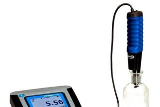
We are going to use a P-AIN Analog input Add-on instruction to configure the temperature transmitter in studio 5000.

We will learn the Analog input parameters and their descriptions which we need to configure.

Analog Input Devices in Studio 5000

Follow the below steps for programming the analog inputs in studio 5000 using the add-on instructions.

Step 1: Open Logix designer and open the PlantPAx Project file in which all required add-on blocks of the PlantPAx library are imported.

call the routine using JSR Instruction

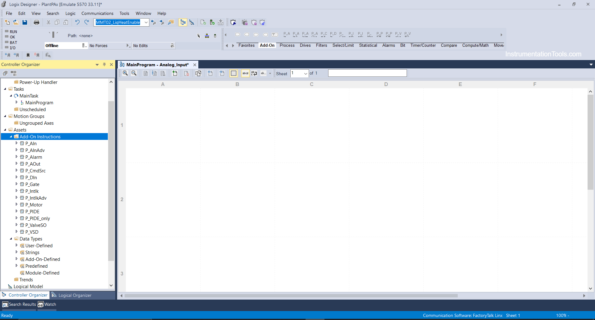
Step 2: Right Click on Main Program and create a new routine as Analog input.

Analog Input Devices in Studio 5000

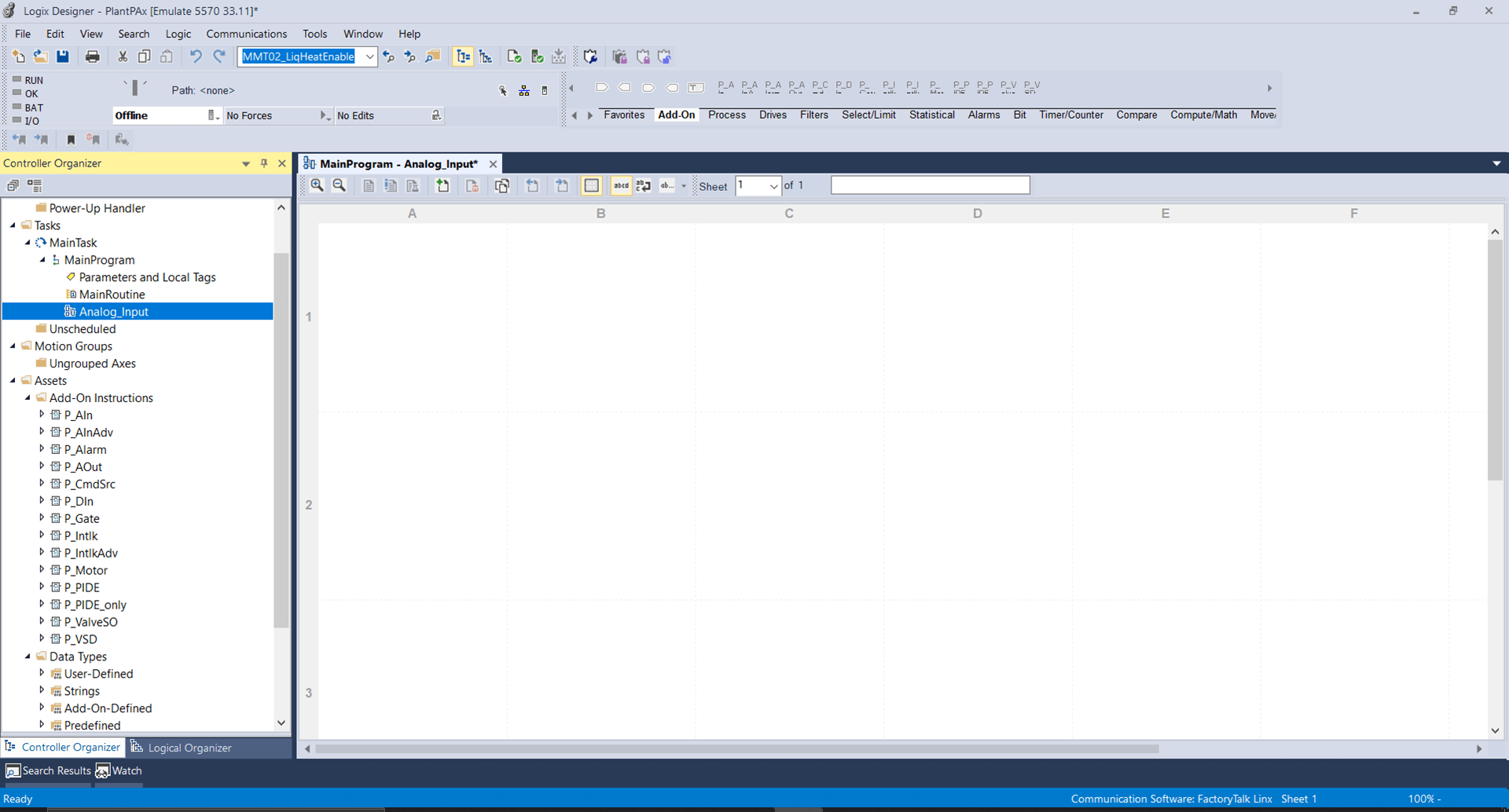
And in the main program, call the routine using JSR Instruction as shown below.

P_AIN instruction

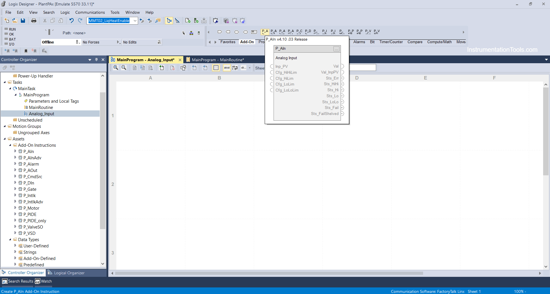
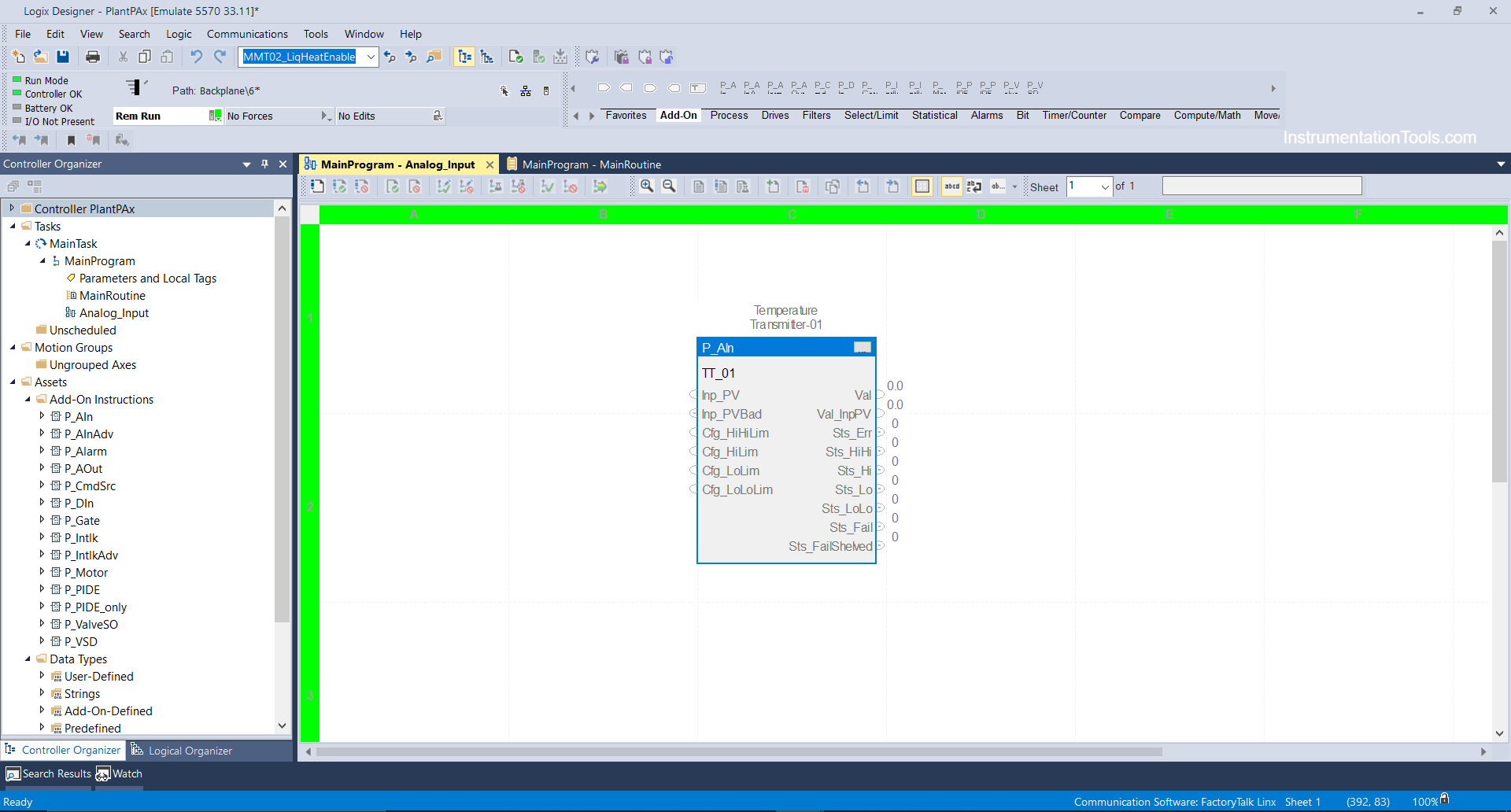
Step 3: Double click on the Analog input routine and click the add-on menu and select P-AIN instruction as shown below.

P-AIN instruction in Studio 5000

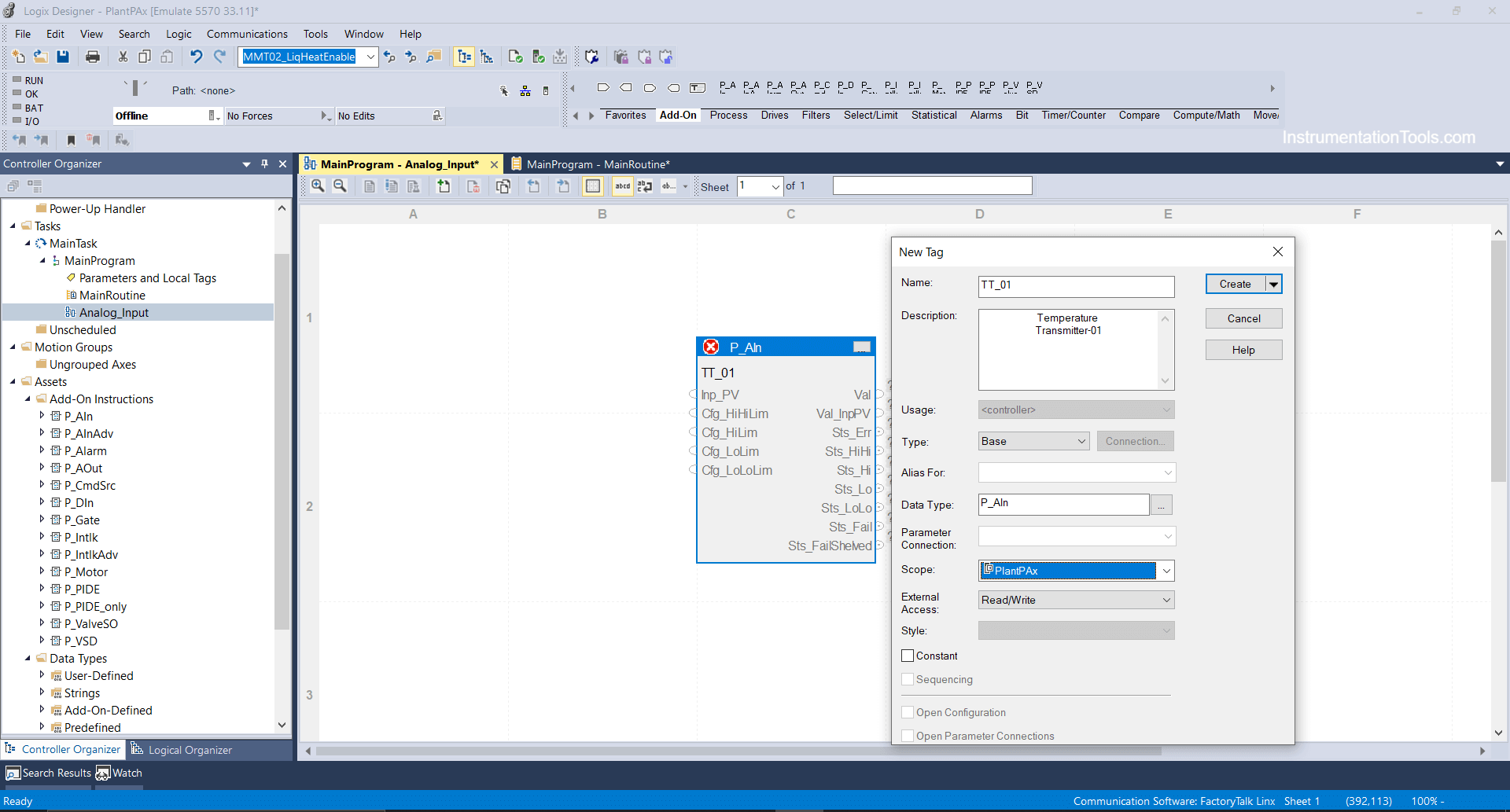
Step 4: After adding the P_AIN block we will bind a tag as TT_01 (temperature transmitter 01) in the controller scope.

Add On Instructions in Studio 5000 Programming

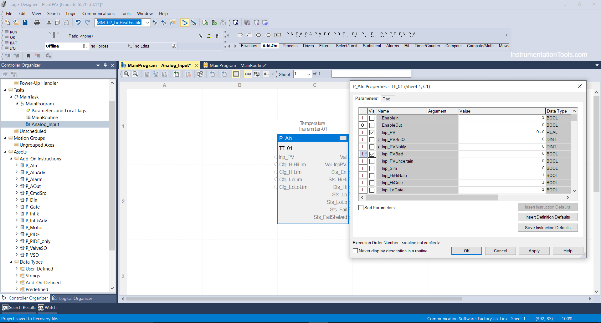
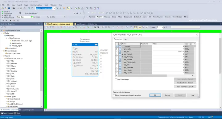
Step 5: After that click on the 3 dots tab and the parameter window will open where you can select the parameters you want.

parameters in logix designer

Inp_PV: It indicates Process Variable input coming from the sensor and can be scaled at the value we will enter. Say if the temperature transmitter range is 0°C to 100°C then it will be scaled at 4ma-20ma in 0 to 30840 engineering Value.

Cfg-HIHILim: It indicates the Configuration of the HIHI limit of the temperature transmitter where you can enter the value of the HIHI limit you want to set. e.g., You can enter 98 ° because 2 ° will be your dead band value.

Cfg-HILim: It indicates the Configuration of the HI limit of the temperature transmitter where you can enter the value of the HI limit you want to set. E.g., You can enter 96°.

therefore, same you can enter the values for LOLO and LO limit.

Val: It indicates an analog value that is substituted through input process value coming from the sensor.

Val Inp-PV: It indicates the actual input value before substitute.

Sts-Err: It indicates a status error if input PV is bad if there is input failure in the actual transmitter from the field side or if there is physical damage in the transmitter.

Sts-HIHI-HI-LOLO-LO: It indicates HIHI-HI-LOLO-LO values if the temperature reaches at actual limits defined.

Sts-Fail-Shelved: It indicates if the alarm has generated bad Input PV or Input failure and has been shelved or masked by the operator.

Step 6: Now we are going to enter raw count and its eng value accordingly which actual transmitter will read values from the field.

Temperature Transmitter Configuration in Studio 5000

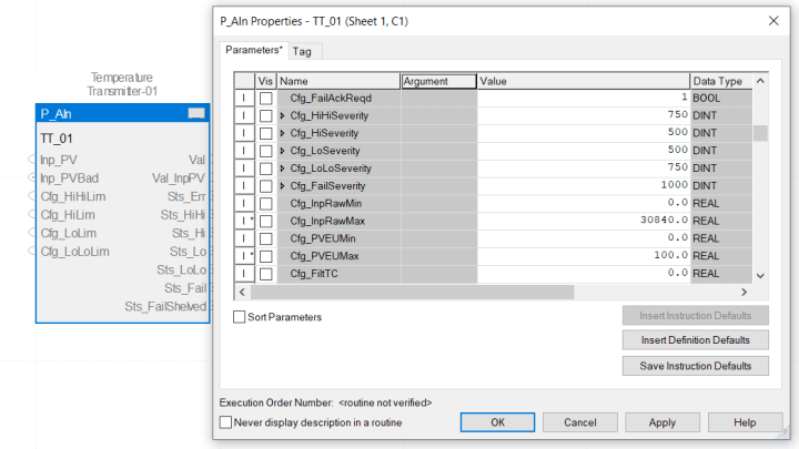
Enter 0 to 30840 in Raw min and Raw max as shown above and 0 to 100 will be your actual temperature transmitter range.

Step 7: Your transmitter is configured you can test as shown below, download the logic file in your available controller or in the emulator as I have done.

Transmitter Configured in Logix Designer

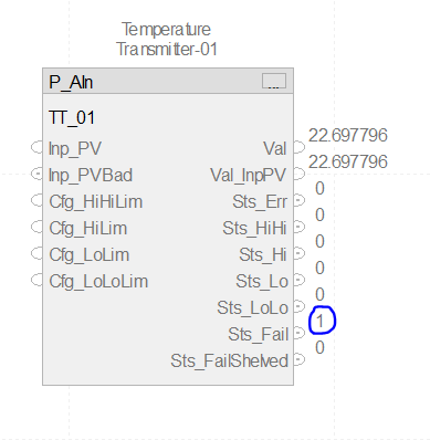
Step 8: After going online in run mode click on the 3 dots tab i.e parameter tab you can enter the values in the Input PV bar as you can see I have entered 7000 i.e 22.69 °C, same you can enter 15000 it will be around 50 °C same you can enter and scale to test the block.

Analog Inputs in PlantPax

Note: I do not have PLC and I have not mapped the Transmitter in the channel slot in the input card so I’m Forcing the value.

If your temperature transmitter is mapped and hardwired IO then it will not let you force or mask the value. You will directly view the value coming from the field.

Consider your Input PV is bad, or your transmitter has a fault, it will show as status fail Sts-Fail=1

transmitter has fault

In the same way, you can check the current situation or values for HIHI-HI-LO-LOLO limits.

If you liked this article, then please subscribe to our YouTube Channel for Electrical, Electronics, Instrumentation, PLC, and SCADA video tutorials.

You can also follow us on Facebook and Twitter to receive daily updates.

Read Next:

  • PlantPAx Control System
  • Import PlantPAx Library
  • DCS Technical Evaluation
  • Download PlantPAx Library
  • Compressor Start Permissive
Don't Miss Our Updates
Be the first to get exclusive content straight to your email.
We promise not to spam you. You can unsubscribe at any time.
Invalid email address
You've successfully subscribed !

Continue Reading

Control Systems Interview Questions & Answers
What is Override Control? – Need & Applications
What is PID Controller Bumpless Transfer ?
What is Nest Loading? – DCS and PLC Control Systems
DCS Troubleshooting Control Valve Loop
Proportional-only Control Theory
Share This Article
Facebook Whatsapp Whatsapp LinkedIn Copy Link
Share
Leave a Comment

Leave a Reply Cancel reply

Your email address will not be published. Required fields are marked *

Stay Connected

128.3kFollowersLike
69.1kFollowersFollow
210kSubscribersSubscribe
38kFollowersFollow

Categories

Explore More

PID Simulator Download
Instrument Loop Test Requirements and Operation Procedures
Understanding Emergency Shutdown Button Installation (ESD)
Ratio Controller Example
Basic Process Control System
What is a Annunciator Panel?
Problem in Water Level Control System
Difference between Cold Standby and Hot Standby

Keep Learning

Variable Speed Control of Propulsion Motor for VSI and CSI type Frequency Converters

Speed Control of Ship Electrical Motor Propulsion

Grounding Components

Selection of Components Used In Electrical Earthing or Grounding

PID Controller Tunning Manually

PID Controller Parameters Tuning Manually

Transmitter Indicators

What is Indicator ?

System architecture

Types of System Architecture used in Industrial Automation

Functional Safety Terms in Industrial Automation

Functional Safety Terminology in Industrial Automation

Why 24 Volts DC Power Supply

Why 24 Volts DC Power Supply is used? – Industrial Automation Systems

Impressed Current Galvanic System

Types of Cathodic Protection for Pipeline Protection

Learn More

Instrumentation Books Free Download

Instrumentation Books Download

PID parameters

PID in Siemens TIA Portal

Opposite Acting Valves

What is Split Range Control Loop ?

Difference between HART and Foundation Fieldbus

Difference between HART and Foundation Fieldbus

Speed Control of Pneumatic Cylinder (Explanation with PLC)

Speed Control of Pneumatic Cylinder (Explanation with PLC)

Electrical and Instrumentation Engineering Documents

Electrical and Instrumentation – Automation Pre-engineering Documents

VFD Braking

DC Injection Braking in VFD

Common Control Valve Problems

Troubleshooting Common Control Valve Problems

Menu

  • About
  • Privacy Policy
  • Copyright

Quick Links

  • Learn PLC
  • Helping Hand
  • Part Time Job

YouTube Subscribe

Follow US
All rights reserved. Reproduction in whole or in part without written permission is prohibited.
Welcome Back!

Sign in to your account

Username or Email Address
Password

Lost your password?