Inst ToolsInst ToolsInst Tools
  • Courses
  • Videos
  • Q & A
    • Interview
      • Instrumentation
      • Electronics
      • Electrical
      • Practical Questions
    • MCQ
      • Instrumentation MCQ
      • Electrical MCQ
      • Electronics MCQ
      • Control Systems MCQ
      • Analog Electronics MCQ
      • Digital Electronics MCQ
      • Power Electronics MCQ
      • Microprocessor MCQ
      • Multiple Choice Questions
  • EE
    • Electronics
      • Electronics Q & A
      • Electronic Basics
      • Electronic Devices & Circuits
      • Electronics Animation
      • Digital Electronics
    • Electrical
      • Electrical Basics
      • Electrical Q & A
      • Power Electronics
      • Electrical Machines
      • Electrical Animation
      • Power Systems
      • Switchgear & Protection
      • Transmission & Distribution
  • Measure
    • Control Valves
    • Calibration
    • Temperature
    • Pressure
    • Flow
    • Level
    • Analyzers
    • Switches
    • Vibration
    • Solenoid Valve
  • Control
    • PLC Tutorials
    • Control Systems
    • Safety Instrumented System (SIS)
    • Communication
    • Fire & Gas System
  • More
    • Design
    • Tools
    • Animation
    • Basics
    • Formulas
    • Standards
    • TextBooks
    • Common
    • Software
    • Excel Tools
    • Erection & Commissioning
    • Process Fundamentals
    • Videos
    • Books
Search
All rights reserved. Reproduction in whole or in part without written permission is prohibited.
Reading: Questions on Dip Tube Type Level System
Share
Notification Show More
Font ResizerAa
Inst ToolsInst Tools
Font ResizerAa
  • Courses
  • PLC Tutorials
  • Control Systems
Search
  • Courses
  • Videos
  • Q & A
    • Interview
    • MCQ
  • EE
    • Electronics
    • Electrical
  • Measure
    • Control Valves
    • Calibration
    • Temperature
    • Pressure
    • Flow
    • Level
    • Analyzers
    • Switches
    • Vibration
    • Solenoid Valve
  • Control
    • PLC Tutorials
    • Control Systems
    • Safety Instrumented System (SIS)
    • Communication
    • Fire & Gas System
  • More
    • Design
    • Tools
    • Animation
    • Basics
    • Formulas
    • Standards
    • TextBooks
    • Common
    • Software
    • Excel Tools
    • Erection & Commissioning
    • Process Fundamentals
    • Videos
    • Books
Follow US
All rights reserved. Reproduction in whole or in part without written permission is prohibited.
Inst Tools > Blog > Practical Questions > Questions on Dip Tube Type Level System

Questions on Dip Tube Type Level System

A liquid storage vessel holding a very corrosive liquid has its level measured by a dip tube type level system.

Last updated: November 20, 2020 3:14 pm
Editorial Staff
Practical Questions
No Comments
Share
4 Min Read
SHARE

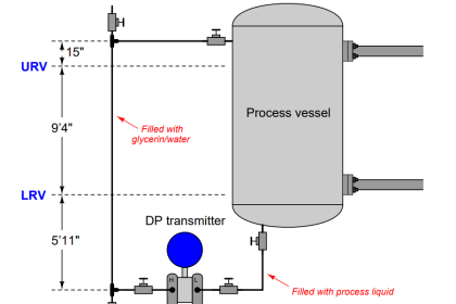
A liquid storage vessel holding a very corrosive liquid has its level measured by a bubbler system, whereby a transmitter measures the backpressure of air inside a “dip tube” inserted into the vessel:

Dip Tube Type Level System

Dip Tube Type Level System

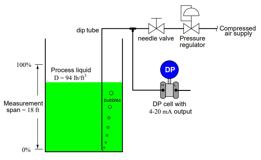
Explain how this level measurement system works, and how it protects the DP cell from the corrosive effects of the process liquid.

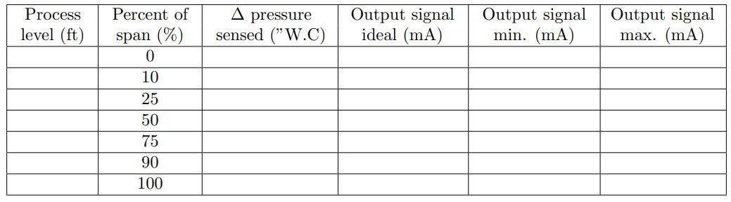
Also, complete a calibration table for the differential pressure transmitter in this level measurement scenario, with a calibration tolerance of ± 0.5%.

Assume that the lower range-value of the process (0% level) is exactly the same height as the bottom of the dip tube:

Electronic transmitter with an output range of 4 to 20 mA

More Questions:

1. The dip tube (or “bubbler”) system does indeed isolate the transmitter from the corrosive process liquid, but how can the dip tube itself survive? And, if the dip tube is able to survive in the corrosive liquid (just like the vessel), why can’t we find a DP cell that can handle it directly without the isolation of a dip tube system?

2. Demonstrate how to estimate numerical answers for this problem without using a calculator.

3. What is your recommendation for setting the position of the needle valve in this bubble tube system? Exactly how far open is “open enough,” and more importantly for what reason?

4. What would happen if the end of the dip tube were to become plugged with debris, blocking all flow?

5. What would happen if the needle valve were to become plugged with debris, blocking all flow?

6. What would happen if the pressure regulator were to become plugged with debris, blocking all flow?

7. Add one or more hand valves to the tubing in this system to provide operators with a simple means of unblocking a plugged dip tube using high-pressure compressed air.

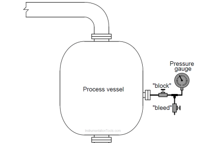
8. Given a 100% full vessel, calculate the amount of pressure that would be registered by a pressure gauge connected to the bottom of the vessel.

9. Given a 100% full vessel, calculate the amount of pressure that would be registered by a pressure gauge connected to the bottom of the dip tube.

10. Given a 100% full vessel, calculate the amount of pressure that would be registered by a pressure gauge connected to the transmitter’s “H” port.

11. Given a 100% full vessel, calculate the amount of pressure that would be registered by a pressure gauge connected to the downstream side of the needle valve.

12. Given a 100% full vessel, calculate the amount of pressure that would be registered by a pressure gauge connected to the upstream side of the needle valve.

Share your answers and explanation with us through the below comments section.

Read Next:

  • Loop Diagram Faults
  • DP transmitter Elevated
  • Thermocouple Details
  • Ultrasonic Sensors Work
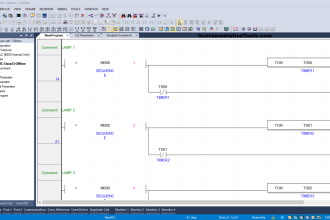
  • PLC Program Problems

Credits: Tony R. Kuphaldt

Don't Miss Our Updates
Be the first to get exclusive content straight to your email.
We promise not to spam you. You can unsubscribe at any time.
Invalid email address
You've successfully subscribed !

Continue Reading

Signal Strength of Guided-wave Radar Level Instrument
Calculation of Hydrostatic Pressure
Calculate LRV and URV for 4-20 mA Loop-powered DP Transmitter
Troubleshoot Allen Bradley PLC Logic
DP transmitter Elevated 10 Feet above the Vessel
How to Connect Proximity Switch (Sink Type) to Make LED ON ?
Share This Article
Facebook Whatsapp Whatsapp LinkedIn Copy Link
Share
Leave a Comment

Leave a Reply Cancel reply

Your email address will not be published. Required fields are marked *

Stay Connected

128.3kFollowersLike
69.1kFollowersFollow
208kSubscribersSubscribe
38kFollowersFollow

Categories

Explore More

Level Measurement Lab Exercise
Purpose of Stop in a Pressure Measuring Instrument
Process Control High Level Alarm Fault Analysis
Example PLC Program
A Series of False Pressure Alarms
Define Normal Status of a Process Switch ?
Programmable Logic Controller (PLC) Questions and Answers – 13
DP Transmitter Located 10 feet Beneath the Vessel
Galileo Thermometer
Measure the Temperature of the RTD

Keep Learning

Calculate DPT Calibrated Range

Calculate the Transmitter Values

Calculate Hydrostatic Pressure of a vertical column of Acetic Acid

Hydrostatic Pressure of a vertical column of Acetic Acid

Heat Exchanger Differential Pressure Transmitter

Heat Exchanger Differential Pressure Transmitter

High and Low Ports on Pneumatic DP Transmitter

Identify High and Low Ports on Pneumatic DP Transmitter

Pressure Transmitter Re-Range Questions

Pressure Transmitter Re-Range Questions

Smart DP transmitter Formula

DP Transmitter Error Calculations

A Question on Steam Drum Water Level Measurement

A Question on Steam Drum Water Level Measurement

Bourdon Tube Gauge Spiral Spring

What is the Purpose of Bourdon Tube Gauge Spiral Spring?

Discover More

Do’s and Don'ts in PLC

Do’s and Don’ts in PLC

double-pumps unit unloading valves

What is an Unloading Valve? – Types, Principle

Analyzers Questions and Answers

Silica Analyzer Questions & Answers

Time Division Multiplexing Objective Questions

Time Division Multiplexing Objective Questions

Difference between Soft Starter and VFD

Difference between Soft Starter and VFD

Types of Sensors used in the Dairy Industry

Types of Sensors used in the Dairy Industry

Power MOSFET Symbols

Power MOSFET – Symbol, Types, Working, Characteristics, Advantages

Typical Switchyard Layout

Electrical Substation – Busbar Arrangements and Layouts

Follow US
All rights reserved. Reproduction in whole or in part without written permission is prohibited.
Welcome Back!

Sign in to your account

Username or Email Address
Password

Lost your password?