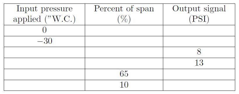
A pneumatic differential pressure transmitter has a calibrated range of −100 to +100 inches of water column (” W.C.), and its output signal range is 3 to 15 PSI.
Complete the following table of values for this transmitter, assuming perfect calibration (no error).
Transmitter
 Develop a linear equation in the form of y = mx + b that directly relates input pressure (x) to output pressure (y).
Demonstrate how to estimate numerical answers for this problem without using a calculator.
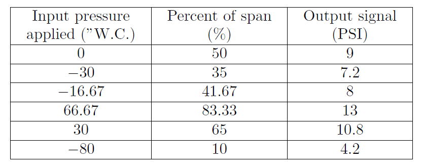
Answer:
Explain the formula used for the above calculations.
Share your answers with us through below comments section.
Read Next:
- Find LRV and URV
- Strain Gauge Principle
- Solenoid Actuated Valves
- Types of Thermometers
- Basics of Hydrostatic
Credits: Tony R. Kuphaldt