Inst ToolsInst ToolsInst Tools
  • Courses
  • Automation
    • PLC
    • Control System
    • Safety System
    • Communication
    • Fire & Gas System
  • Instrumentation
    • Design
    • Pressure
    • Temperature
    • Flow
    • Level
    • Vibration
    • Analyzer
    • Control Valve
    • Switch
    • Calibration
    • Erection & Commissioning
  • Interview
    • Instrumentation
    • Electrical
    • Electronics
    • Practical
  • Q&A
    • Instrumentation
    • Control System
    • Electrical
    • Electronics
    • Analog Electronics
    • Digital Electronics
    • Power Electronics
    • Microprocessor
  • Request
Search
  • Books
  • Software
  • Projects
  • Process
  • Tools
  • Basics
  • Formula
  • Power Plant
  • Root Cause Analysis
  • Electrical Basics
  • Animation
  • Standards
  • 4-20 mA Course
  • Siemens PLC Course
Reading: Control Valve Testing for Noise Measurement
Share
Font ResizerAa
Inst ToolsInst Tools
Font ResizerAa
  • Courses
  • Design
  • PLC
  • Interview
  • Control System
Search
  • Courses
  • Automation
    • PLC
    • Control System
    • Safety System
    • Communication
    • Fire & Gas System
  • Instrumentation
    • Design
    • Pressure
    • Temperature
    • Flow
    • Level
    • Vibration
    • Analyzer
    • Control Valve
    • Switch
    • Calibration
    • Erection & Commissioning
  • Interview
    • Instrumentation
    • Electrical
    • Electronics
    • Practical
  • Q&A
    • Instrumentation
    • Control System
    • Electrical
    • Electronics
    • Analog Electronics
    • Digital Electronics
    • Power Electronics
    • Microprocessor
  • Request
Follow US
All rights reserved. Reproduction in whole or in part without written permission is prohibited.
Inst Tools > Blog > Control Valves > Control Valve Testing for Noise Measurement

Control Valve Testing for Noise Measurement

Learn how to do control valve testing for noise measurement using the test setup and acoustic instrumentation.

Last updated: September 17, 2020 5:24 pm
Editorial Staff
Control Valves
No Comments
Share
5 Min Read
SHARE

Control Valve Noise

The predicted sound pressure level radiated from a control valve is a complex determination, and the allowable noise level in the installed location cannot be stated as one simple number to be specified in all circumstances. This is particularly true where there are other noise sources in close proximity since they have an additive effect.

Contents
Control Valve NoiseTesting Setup

The actual level depends on a number of factors, such as atmospheric discharge, physical location, the proximity of other noise sources and their magnitude, piping system configuration and wall thickness, insulation on piping, presence of reflective sources, etc.

Prediction of noise generated by a control valve is an inexact science. Prediction levels for a valve operation at conditions specified on the specification sheet can vary widely using various manufacturers’ methods.

To provide a basis for allowable noise level analysis, control valves calculated to generate excessive noise levels should have alternate valves proposed that will not exceed 85 dBA at one meter downstream and one meter out from the pipe.

For atmospheric discharge vent control valves (or system), the noise level should not exceed 90 dBA at a point four meters down from the vent exhaust and at a downward angle of 45 degrees.

No allowance should be taken for insulation or increased pipe wall thickness over that specified in making noise calculation, or in the valve or the noise reduction system.

The calculated continuous noise level should not exceed 85 dBA, measured where personnel may be continuously working. This may not be one meter downstream and one meter out from the pipe.

The Occupational Safety and Health Administration decreases the allowable time of exposure as the sound level increases, and the user is referred to as OSHA 1910.95 for specific guidelines. It is the user’s responsibility to determine if the sound level will meet OSHA requirements.

Noise levels above 85 dBA may be allowable where personnel is not working continuously.

The maximum intermittent sound level should normally be limited to 110 dBA.

Documented procedures and computer programs to estimate control valve noise are available from leading manufacturers, and they should be used to determine whether the noise is a consideration. However, noise prediction and mitigation is a specialized effort generally requiring the manufacturer’s recommendation for an effective design.

Valves with noise abatement or cavitation control trim with small passages tend to plug with debris, particularly during startup, and should be protected with conical or T-type strainers.

Testing Setup

The control valve noise test setup consists of a high-pressure source, upstream throttling valve, upstream silencer, test specimen or valve, low-pressure receiver, test chamber, flow, and acoustic instrumentation.

The test setup is shown in the image below.

Control Valve Testing for Noise Measurement

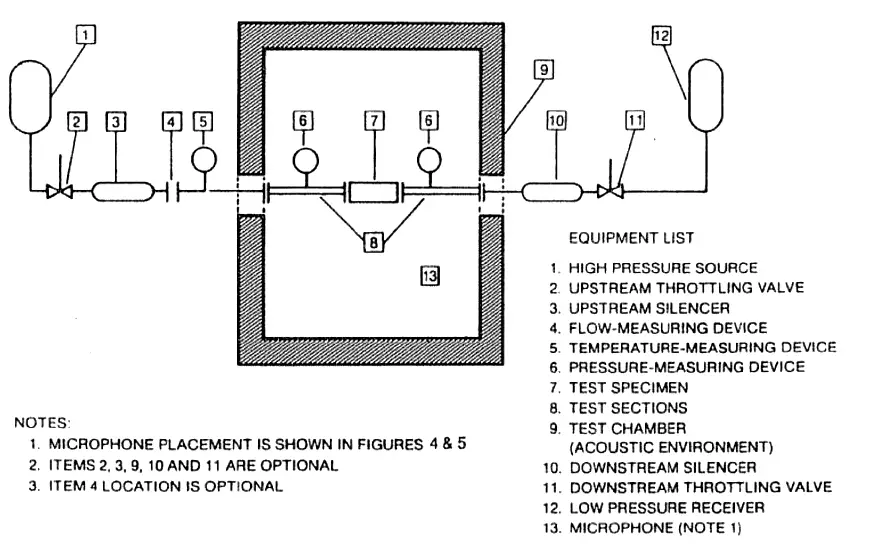
The upstream and downstream throttling valves are required to maintain the required pressure in the test system. If a large pressure drop occurs across the test system then we need an upstream silencer for noise reduction of throttling valves.

The test valve and associated piping should not be insulated. There are no limitations concerning the upstream and downstream piping length requirements. The exposed pipe in the test chamber should be a minimum of 2 meters long and free of mechanical connections.

Piping for each side of the test valve should be schedule 40 steel pipe for valves through 10-inch body size having pressure rating up to ANSI class 600. Piping having 10 mm wall thickness should be used for valve sizes ranging from 12 to 24 inches.

Pressure taps should be provided for the measurement of upstream and downstream pressure. The microphone should be located 1 meter away from the nearest pipe surface.

Read Next:

  • Control Valve Noise
  • Control Valve MCQ
  • Pressure Relief Valve
  • Pneumatic Valve Positioner
  • Solenoid Valve & PLC Wiring
Don't Miss Our Updates
Be the first to get exclusive content straight to your email.
We promise not to spam you. You can unsubscribe at any time.
Invalid email address
You've successfully subscribed !

Continue Reading

Control Valve Characteristics
Classification of Solenoid Valves
Pilot-operated Relief Valve Principle
Digital Control Valves – Introduction, Principle, Setup, Applications
What is a 3-way Solenoid Valve ?
Applications of Needle Valves
Share This Article
Facebook Whatsapp Whatsapp LinkedIn Copy Link
Share
Leave a Comment

Leave a Reply Cancel reply

Your email address will not be published. Required fields are marked *

Stay Connected

128.3kFollowersLike
69.1kFollowersFollow
210kSubscribersSubscribe
38kFollowersFollow

Categories

Explore More

Solenoid Valve Failure in Plant Start-Up: Identifying the Root Cause
Solenoid Valve’s Energized or De-energized State ?
Basics of Actuators
Solenoid Valve with Manual Reset Working Principle
How to Choose a Control Valve?
Calculate Flow Coefficient Kv of Solenoid Valve
Solving Control Valve Hunting: Instrument Troubleshooting
Solenoid Valve Problems and Solutions

Keep Learning

Ball Valve Material Selection

Ball Valve Material Selection

ON OFF Valve Parts

ON OFF Valve Preventive Maintenance and Testing Procedure

Valve Leakage Tests

Types of Valve Leakage Tests

Direct Lift Diaphragm Normally Open Solenoid Valve

Direct Lift Diaphragm Solenoid Valve Principle

valve plug and seat damage

Control Valve Erosion Problems

Needle Valve Schematic

How Needle Valve Works ?

Root Cause Analysis on Hunting of Control Valves

Hunting of Control Valves

Pinch Valve

What is Pinch Valve ?

Learn More

Limit, Selector, and Override controls

Limit, Selector, and Override controls

Temperature and Humidity Objective Questions

Temperature and Humidity Objective Questions

Digital Electronics Multiple Choice Questions

Random Access Memory Objective Questions – Part 4

Battery in Vehicle

Why is a Battery used in a Vehicle?

Switches, Repeaters, Bridges, Routers, Firewalls

Switches, Repeaters, Bridges, Routers, Firewalls

Flange Types and Definitions

Flange Types and Definitions

Categories of Unshielded Twisted Pair

Network Cabling

Control Valve Calibration

How-to do Control Valve Calibration?

Menu

  • About
  • Privacy Policy
  • Copyright

Quick Links

  • Learn PLC
  • Helping Hand
  • Part Time Job

YouTube Subscribe

Follow US
All rights reserved. Reproduction in whole or in part without written permission is prohibited.
Welcome Back!

Sign in to your account

Username or Email Address
Password

Lost your password?