Inst ToolsInst ToolsInst Tools
  • Courses
  • Automation
    • PLC
    • Control System
    • Safety System
    • Communication
    • Fire & Gas System
  • Instrumentation
    • Design
    • Pressure
    • Temperature
    • Flow
    • Level
    • Vibration
    • Analyzer
    • Control Valve
    • Switch
    • Calibration
    • Erection & Commissioning
  • Interview
    • Instrumentation
    • Electrical
    • Electronics
    • Practical
  • Q&A
    • Instrumentation
    • Control System
    • Electrical
    • Electronics
    • Analog Electronics
    • Digital Electronics
    • Power Electronics
    • Microprocessor
  • Request
Search
  • Books
  • Software
  • Projects
  • Process
  • Tools
  • Basics
  • Formula
  • Power Plant
  • Root Cause Analysis
  • Electrical Basics
  • Animation
  • Standards
  • 4-20 mA Course
  • Siemens PLC Course
Reading: What is a Watchdog Timer in PLC?
Share
Notification Show More
Font ResizerAa
Inst ToolsInst Tools
Font ResizerAa
  • Courses
  • Design
  • PLC
  • Interview
  • Control System
Search
  • Courses
  • Automation
    • PLC
    • Control System
    • Safety System
    • Communication
    • Fire & Gas System
  • Instrumentation
    • Design
    • Pressure
    • Temperature
    • Flow
    • Level
    • Vibration
    • Analyzer
    • Control Valve
    • Switch
    • Calibration
    • Erection & Commissioning
  • Interview
    • Instrumentation
    • Electrical
    • Electronics
    • Practical
  • Q&A
    • Instrumentation
    • Control System
    • Electrical
    • Electronics
    • Analog Electronics
    • Digital Electronics
    • Power Electronics
    • Microprocessor
  • Request
Follow US
All rights reserved. Reproduction in whole or in part without written permission is prohibited.
Inst Tools > Blog > PLC Tutorials > What is a Watchdog Timer in PLC?

What is a Watchdog Timer in PLC?

Watchdog timer helps to reset the CPU errors which occur during scan time so that the PLC starts working again without any manual reset.

Last updated: March 4, 2021 11:14 am
Editorial Staff
PLC Tutorials
No Comments
Share
3 Min Read
SHARE

In this article, we will learn about a watchdog timer in the Siemens PLC.

As we know that in the PLC when CPU process the logic it takes a certain amount of the time.

The amount of time the CPU takes to process the logic depends on the size of the program.

So, scanning from the first network to the end of the program is called one scan cycle.

For one scan cycle, time must not exceed defined cycle time and amount of time it takes to process the logic.

Watchdog Timer in PLC

To check a cycle time open TIA portal.

In the programming environment go to the main CPU. Do a right-click and click on online and diagnostics.

online and diagnostics

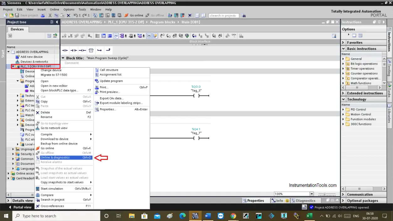
The following new window will open up. Choose the cycle time option from it.

One thing to note is that to see cycle time you must have to stay in the online mode. In the offline mode, you won’t see anything.

Watchdog Timer in PLC

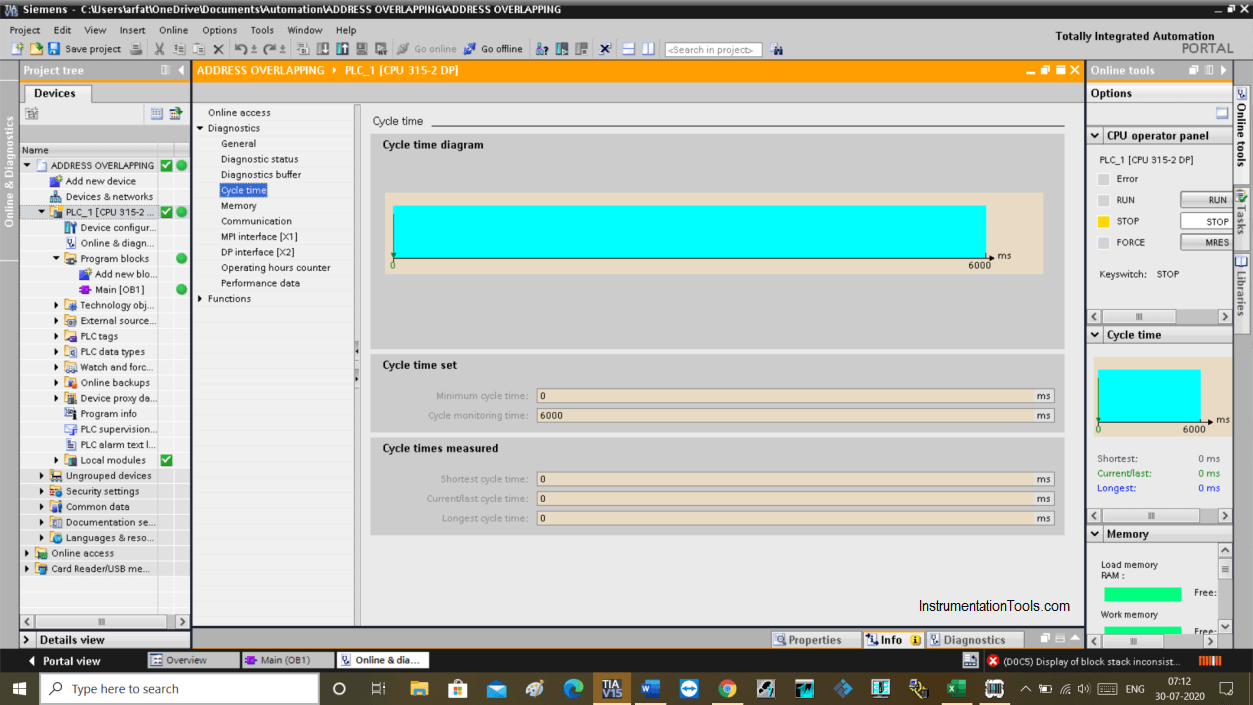
In the above window, you can see a cycle time. In the cycle time measured tab, you can see a cycle time of the current program.

In the cycle time set option, the maximum time limit Is set to 6000ms means 6 seconds. This is a scan time for one cycle.

So, while execution if cycle time exceeds 6000ms then it generates an error.

Here, it comes to the watchdog timer concept. Based on a scan time when the CPU executes the logic this electronic timer starts to calculate time in the background.

If cycle time exceeds more than defined time, this electronic timer produced an error.

So for this to work, the timer starts timing from the first network and reset its timing at the end of the network.

Due to programming error or any hardware error if the CPU fails to reset the timer then it produces a time-out error.

Watchdog timer helps to reset the CPU when these types of errors occur so that the PLC starts working again without any manual reset. If the errors occur repeatedly then the watchdog timer may not helpful, human intervention is required to troubleshoot the problem.

The scan time varies from cycle to cycle because sometime FCs and FBs are not executed, or due to the manual mode of the PID loops.

This is how watchdog timer works in the background while the execution of the program.

Author: Suhel Patel

If you liked this article, then please subscribe to our YouTube Channel for PLC and SCADA video tutorials.

You can also follow us on Facebook and Twitter to receive daily updates.

Read Next:

  • What is PLC Scan Time?
  • S7 1500 PLC Simulator
  • Siemens Peripheral IOs
  • Basics of DDE Protocol
  • Trends in SCADA System
Don't Miss Our Updates
Be the first to get exclusive content straight to your email.
We promise not to spam you. You can unsubscribe at any time.
Invalid email address
You've successfully subscribed !

Continue Reading

Write a PLC Program for Selector Machine using Structured Text
Power Supply Sizing for Industrial Automation Systems
Comparing ICS and IT Systems Security
Mitsubishi PLC Programming Tutorials
PLC based Door Open and Closing System
PLC Motor Control Ladder Logic Programming
Share This Article
Facebook Whatsapp Whatsapp LinkedIn Copy Link
Share
Leave a Comment

Leave a Reply Cancel reply

Your email address will not be published. Required fields are marked *

Stay Connected

128.3kFollowersLike
69.1kFollowersFollow
210kSubscribersSubscribe
38kFollowersFollow

Categories

Explore More

How to take Backup from Siemens S7-300 PLC?
What is a Wet Contact? – Basics of PLC Wiring
Mail Box Automation: Programming with Schneider PLC
Up Counter PLC Program
PLC Programming Example with Pushbutton and Motor
Most Asked Questions on SCADA with Answers
Real-time PLC Projects – Industrial Automation
Upgrading and Migration of PLC Systems

Keep Learning

Example of PID Control Instruction

How to Configure PID in Siemens PLC?

Simple Conveyor Control PLC Program

XG5000 Example of Simple Conveyor Control PLC Program

Digital input signals in safety circuits

1oo2 Evaluation Safety Instruction in Safety PLC

LCS Configuration equipped with LOTO Facility

Motor Control Signal Interface

Wood Sawing and Blower System PLC Control Design

Wood Sawing and Blower System: PLC Control Design

PLC Star-Delta starter with interlock

Schneider PLC Example Program for Star-Delta System

Automatic Packing of Bottles

Automatic Packing of Bottles Programming

Free WinCC SCADA Training Course

Free SCADA Training Course

Learn More

Flow meters Tube Fittings

Sanitary Pipe Fittings for the Instruments

diaphragm-pressure-gauge

Diaphragm Pressure Sensors

Power Electronics Objective Questions

Thyristor Mounting Objective Questions and Answers

Learn PLC in Hindi

Learn PLC in Hindi

Properties of Conducting Materials

Resistivity

4-20mA Current Loop

Basics of 4-20mA Current Loop

To check the characteristic of vibration probe

Bently Nevada Vibration Probes Functional Testing

Boiler Feed Water Circulation System

Boiler Feed Water Circulation System

Menu

  • About
  • Privacy Policy
  • Copyright

Quick Links

  • Learn PLC
  • Helping Hand
  • Part Time Job

YouTube Subscribe

Follow US
All rights reserved. Reproduction in whole or in part without written permission is prohibited.
Welcome Back!

Sign in to your account

Username or Email Address
Password

Lost your password?