Inst ToolsInst ToolsInst Tools
  • Ask
  • Courses
  • Videos
  • Q & A
    • Interview
      • Instrumentation
      • Electronics
      • Electrical
      • Practical Questions
    • MCQ
      • Instrumentation MCQ
      • Electrical MCQ
      • Electronics MCQ
      • Control Systems MCQ
      • Analog Electronics MCQ
      • Digital Electronics MCQ
      • Power Electronics MCQ
      • Microprocessor MCQ
      • Multiple Choice Questions
  • EE
    • Electronics
      • Electronics Q & A
      • Electronic Basics
      • Electronic Devices & Circuits
      • Electronics Animation
      • Digital Electronics
    • Electrical
      • Electrical Basics
      • Electrical Q & A
      • Power Electronics
      • Electrical Machines
      • Electrical Animation
      • Power Systems
      • Switchgear & Protection
      • Transmission & Distribution
  • Measure
    • Control Valves
    • Calibration
    • Temperature
    • Pressure
    • Flow
    • Level
    • Analyzers
    • Switches
    • Vibration
    • Solenoid Valve
  • Control
    • PLC Tutorials
    • Control Systems
    • Safety Instrumented System (SIS)
    • Communication
    • Fire & Gas System
  • More
    • Design
    • Tools
    • Animation
    • Basics
    • Formulas
    • Standards
    • TextBooks
    • Common
    • Software
    • Excel Tools
    • Erection & Commissioning
    • Process Fundamentals
    • Videos
    • Books
Search
All rights reserved. Reproduction in whole or in part without written permission is prohibited.
Reading: Calibration Procedure of Voltmeter and Ammeter
Share
Notification Show More
Font ResizerAa
Inst ToolsInst Tools
Font ResizerAa
  • Courses
  • PLC Tutorials
  • Control Systems
Search
  • Ask
  • Courses
  • Videos
  • Q & A
    • Interview
    • MCQ
  • EE
    • Electronics
    • Electrical
  • Measure
    • Control Valves
    • Calibration
    • Temperature
    • Pressure
    • Flow
    • Level
    • Analyzers
    • Switches
    • Vibration
    • Solenoid Valve
  • Control
    • PLC Tutorials
    • Control Systems
    • Safety Instrumented System (SIS)
    • Communication
    • Fire & Gas System
  • More
    • Design
    • Tools
    • Animation
    • Basics
    • Formulas
    • Standards
    • TextBooks
    • Common
    • Software
    • Excel Tools
    • Erection & Commissioning
    • Process Fundamentals
    • Videos
    • Books
Follow US
All rights reserved. Reproduction in whole or in part without written permission is prohibited.
Inst Tools > Blog > Calibration > Calibration Procedure of Voltmeter and Ammeter

Calibration Procedure of Voltmeter and Ammeter

Last updated: April 10, 2020 6:29 pm
Editorial Staff
Calibration
No Comments
Share
3 Min Read
SHARE

Study about the calibration procedure of voltmeter and ammeter using master instruments like multi-function calibrators.

Contents
What is Voltmeter?What is Ammeter?Master Instruments With Auxiliary:Multi-Function Calibrator (5 ½ MFC)WiresCrocodile PinsSetup for VoltmeterVoltmeter Calibration ProcedureCalibration Certificate of VoltmeterSetup for AmmeterAmmeter Calibration ProcedureCalibration Certificate of AmmeterRead Next:

What is Voltmeter?

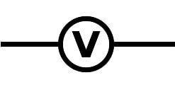
A Voltmeter is also known as a Voltage Meter, it is an instrument used for measuring the potential difference or voltage between two points in an electrical or electronic circuit. They can be used in AC/DC circuits.

Symbolic Representation:

Voltmeter Symbol

What is Ammeter?

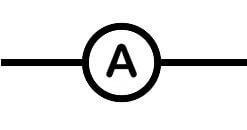
An Ammeter is also known as an Ampere Meter, it is an instrument used for measuring the current. The measuring range of the ammeter depends on the resistance (CT) inside the Ammeter.

Symbolic Representation:

ammeter Symbol

Master Instruments With Auxiliary:

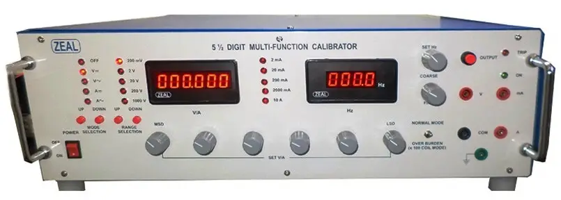
Multi-Function Calibrator (5 ½ MFC)

The Multi-Function Calibrator (MFC) is the instrument used as a source supplier for AC/DC voltage and Current for the calibration of all the electrical related devices.

Multi-Function Calibrator

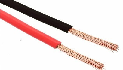
Wires

Wires

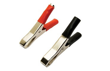
Crocodile Pins

Crocodile Pins

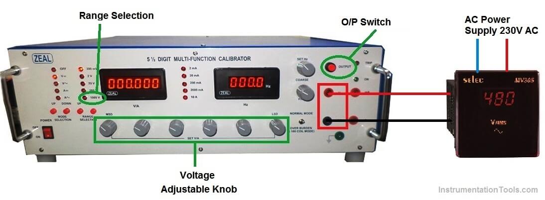
Setup for Voltmeter

Voltmeter Calibration

Voltmeter Calibration Procedure

We will perform the individual calibration of Voltmeter and Ammeter.

1. Connect the wire with the help of crocodile pin to Voltmeter one end and other to the 5 ½ MFC meter as shown in the above Setup picture.

2. Here we will keep the Source meter i.e. 5 ½ MFC meter as a fixed voltage supplier and will see the reading on the UUC (Unit Under Calibration – voltmeter)

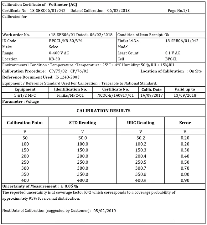
3. Suppose we have a Voltmeter with Specification.

  • Make- Selec
  • Range-0 to 400V AC
  • Least Count- 0.1V AC

4. We will supply the AC voltage with the help of Knob provided on the 5 ½ MFC meter in the increment of 50V AC. i.e. 50,100,150,200,250 VAC etc.

5. And will record what is the UUC instrument is displaying on its display.

6. Repeat the 4th step till the Max limit of Voltmeter Range reaches.

Calibration Certificate of Voltmeter

Calibration Certificate of Voltmeter

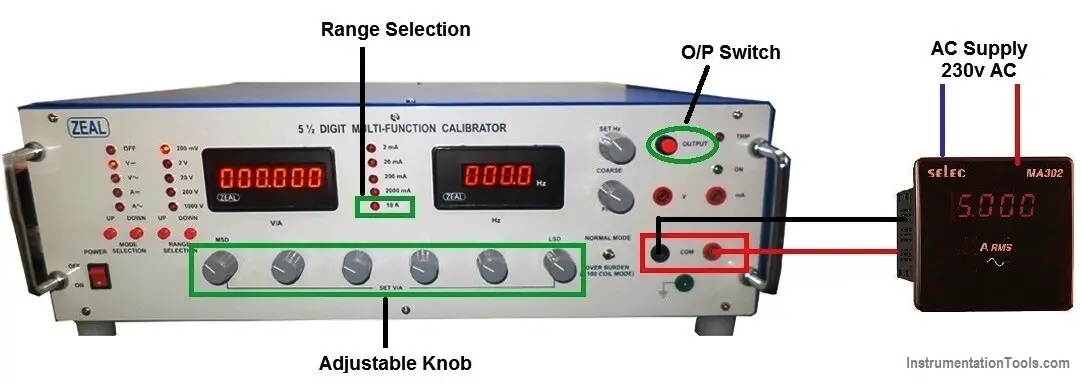
Setup for Ammeter

Ammeter Calibration Procedure

Ammeter Calibration Procedure

1. Connect the wire with the help of crocodile pin to Ammeter one end and other to the 5 ½ MFC meter as shown in the above Setup picture.

2. Here we will keep the Source meter i.e. 5 ½ MFC meter as a fixed Ampere supplier and will see the reading on the UUC (Unit Under Calibration)

3. Suppose we have an Ammeter with Specification.

  • Make- Selec
  • Range-0 to 10 Amp DC
  • Least Count- 1 Amp DC

4. We will supply the DC Current with the help of Knob provided on the 5 ½ MFC meter in the increment steps like i.e. 2, 4, 6, 8, 10.

5. And will record what is the UUC instrument (ammeter) is displaying on its display.

6. Repeat the 4th step till the Max limit of Ammeter Range reaches.

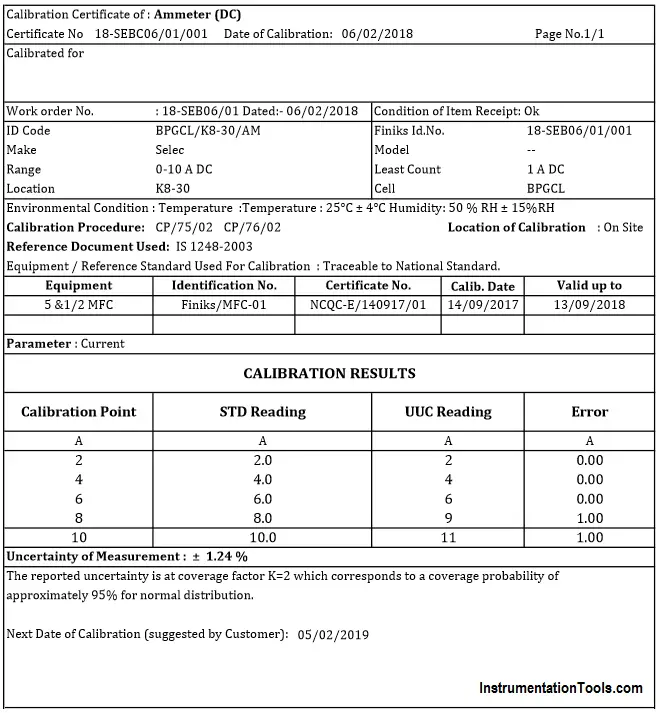
Calibration Certificate of Ammeter

Calibration Certificate of Ammeter

Author: Jadhav Amit R

Read Next:

  • Digital Control Valve Calibration
  • Pressure Gauge Calibration
  • Analyzer Principle and Calibration
  • Portable Gas Detectors Calibration
  • Turbidity Sensor Calibration
Don't Miss Our Updates
Be the first to get exclusive content straight to your email.
We promise not to spam you. You can unsubscribe at any time.
Invalid email address
You've successfully subscribed !
How to Calibrate Oxygen Analyzer? – O2 Sensor Testing Procedure
Calibration of Pyrometers using Black Body
Different Types of Temperature Calibrators
Ammonia Gas Detector Working Principle and Calibration
Prover Tank Calibration and Mass Flow Meter Verification Procedure
Share This Article
Facebook Whatsapp Whatsapp LinkedIn Copy Link
Share
Leave a Comment

Leave a Reply Cancel reply

Your email address will not be published. Required fields are marked *

Stay Connected

128.3kFollowersLike
69.1kFollowersFollow
208kSubscribersSubscribe
38kFollowersFollow

Categories

Recent Comments

  • Kamli on Top Free PLC Software
  • Guifty Shimica on Top Non-PLC Certification Courses for Automation Professionals
  • Guifty Shimica on Top Non-PLC Certification Courses for Automation Professionals
  • MIHARITSOA Aina Sitraka on Top Non-PLC Certification Courses for Automation Professionals

Related Articles

Displacement Level Transmitter in situ calibration

Displacer (buoyancy) Level Transmitter Principle, Limitations, Design, Installation & Calibration

ORP-sensor-calibration

Oxidation-Reduction Potential (ORP) Sensor Calibration Procedure

Functional Testing of Control Valve Positioners

Functional Testing of Control Valve Positioners

Installation and Calibration of Pressure Transmitter

Installation and Calibration of Pressure Transmitter

process chemical analyzer calibration

Automated Calibration

Fieldbus Transmitter Calibration

Fieldbus Transmitters Calibration and Ranging

Difference between Repeatability and Reproducibility

Difference between Repeatability and Reproducibility

Pig Signalling Switches Functional Testing

Pig Signalling Switches Functional Testing

More Articles

DP-Level-Measurement-Calculation-Above-Tapping-Point-Open-Tank

Differential Pressure (DP) Level transmitter Installed Above Tapping Point

Why does SMPS Need isolation - Switch Mode Power Supply

Why does SMPS Need isolation? – Switch Mode Power Supply

Power MOSFET Safe Operating Area

Power MOSFET Safe Operating Area

Transmission and Distribution Interview Questions

Measurement and Instrumentation Objective Questions – Part 3

Relay Parts

Difference Between NO and NC Contacts

7 Marketing Strategies for Engineering Companies

7 Marketing Strategies for Engineering Companies

Swiss Screw Machining

Things You Should Know About Swiss Screw Machining

Failure Demand in Safety Control Circuit

Safety Instrumented System Module Failure

Follow US
All rights reserved. Reproduction in whole or in part without written permission is prohibited.
Welcome Back!

Sign in to your account

Username or Email Address
Password

Lost your password?