This article is about a pulse generation PLC program using Siemens TIA PORTAL.
In industries, we use special audio and visual indications to notify the operators about the alarms and trips of the process. Different types of indications are flashing LED, beacons with different tones, etc.
We can set the rate of pulses from slow to fast as per our requirement by changing the timing of the timers. Here we will be discussing the pulse generation using timer instruction in Siemens PLC.
Below I have explained the PLC program for pulse generation.
Inputs and Outputs
- Inputs: START(I0.0), STOP (I0.1)
- Outputs: LED_INDICATION (Q0.0)
- Timers: T0 & T1
- Memory Bit: M0.0
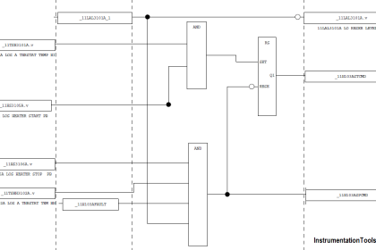
Pulse Generation using Timer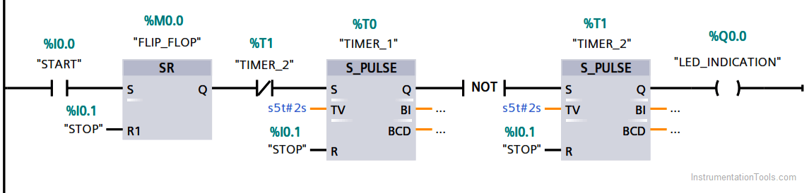
Description
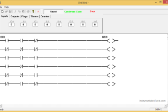
When you press the start button (%I0.0), then the flip-flop (M0.0) energizes then it will pass the signal through NC contact of timer (T2) then timer 1 will energize.
Here I have used S_Pulse timer which will run in our case for 2 seconds after 2 seconds timer will energize.
We can change the timing of the timer to change the flashing rate as per our requirement.
If Timer 1 is not energized then first NOT instruction will energize the Timer 2 allowing output to turn ON for 2 seconds.
Both the timers will run for 2 seconds simultaneously allowing LED to turn ON and OFF for every 2 seconds thus flashing the LED.
Author: Suhel Patel
If you liked this article, then please subscribe to our YouTube Channel for PLC and SCADA video tutorials.
You can also follow us on Facebook and Twitter to receive daily updates.
Read Next:
- Troubleshoot PLC Program
- Protect PLC using Password
- PLC Maths Instructions
- JUMP Instruction in PLC
- Siemens S7 1200 PLC
- One-Shot Rising PLC Logic


Hi,
What is the need of two timers?
To generate the pulses, 1 timer stay ON for 2 sec, so another timer will remain OFF for 2 sec. thus generating pulse for that interval
Let me correct if my and is wrong…. I think of one timer is enough for pulse generation of every two Seconds once… I will explain, after sr flipflop take contact of timer 1 NC CONTACT., when we press start sr FF will energized and start timer. 2 second after timer output goes to led to blink and timer contact which we taken on After flipflop.,it change from nc to open and again change to NC then again timer start and 2sec after led blink and this operation is continuously running….