Inst ToolsInst ToolsInst Tools
  • Courses
  • Videos
  • Q & A
    • Interview
      • Instrumentation
      • Electronics
      • Electrical
      • Practical Questions
    • MCQ
      • Instrumentation MCQ
      • Electrical MCQ
      • Electronics MCQ
      • Control Systems MCQ
      • Analog Electronics MCQ
      • Digital Electronics MCQ
      • Power Electronics MCQ
      • Microprocessor MCQ
      • Multiple Choice Questions
  • EE
    • Electronics
      • Electronics Q & A
      • Electronic Basics
      • Electronic Devices & Circuits
      • Electronics Animation
      • Digital Electronics
    • Electrical
      • Electrical Basics
      • Electrical Q & A
      • Power Electronics
      • Electrical Machines
      • Electrical Animation
      • Power Systems
      • Switchgear & Protection
      • Transmission & Distribution
  • Measure
    • Control Valves
    • Calibration
    • Temperature
    • Pressure
    • Flow
    • Level
    • Analyzers
    • Switches
    • Vibration
    • Solenoid Valve
  • Control
    • PLC Tutorials
    • Control Systems
    • Safety Instrumented System (SIS)
    • Communication
    • Fire & Gas System
  • More
    • Design
    • Tools
    • Animation
    • Basics
    • Formulas
    • Standards
    • TextBooks
    • Common
    • Software
    • Excel Tools
    • Erection & Commissioning
    • Process Fundamentals
    • Videos
    • Books
Search
All rights reserved. Reproduction in whole or in part without written permission is prohibited.
Reading: Inductively Coupled Wire Guided Float Detectors
Share
Notification Show More
Font ResizerAa
Inst ToolsInst Tools
Font ResizerAa
  • Courses
  • PLC Tutorials
  • Control Systems
Search
  • Courses
  • Videos
  • Q & A
    • Interview
    • MCQ
  • EE
    • Electronics
    • Electrical
  • Measure
    • Control Valves
    • Calibration
    • Temperature
    • Pressure
    • Flow
    • Level
    • Analyzers
    • Switches
    • Vibration
    • Solenoid Valve
  • Control
    • PLC Tutorials
    • Control Systems
    • Safety Instrumented System (SIS)
    • Communication
    • Fire & Gas System
  • More
    • Design
    • Tools
    • Animation
    • Basics
    • Formulas
    • Standards
    • TextBooks
    • Common
    • Software
    • Excel Tools
    • Erection & Commissioning
    • Process Fundamentals
    • Videos
    • Books
Follow US
All rights reserved. Reproduction in whole or in part without written permission is prohibited.
Inst Tools > Blog > Level Measurement > Inductively Coupled Wire Guided Float Detectors

Inductively Coupled Wire Guided Float Detectors

Last updated: December 14, 2019 9:54 am
Editorial Staff
Level Measurement
No Comments
Share
3 Min Read
SHARE

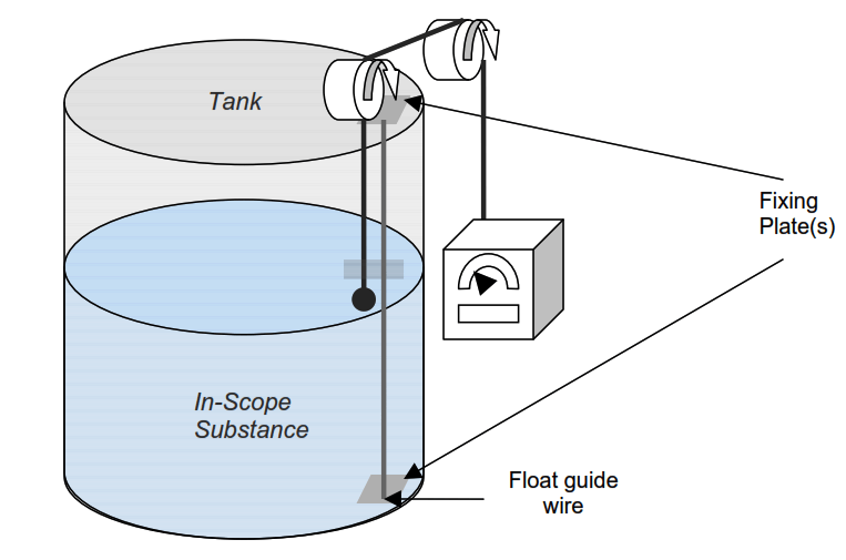
Inductively Coupled Wire Guided Float Detectors is an old method of level measurement used in the fuel storage industry. This system has a wire that is fixed at both the top and bottom of the tank and is used as a guide and a source of power for the float. The float contains an inductively coupled transducer, powered by the guide-wire.

Contents
Wire Guided Float DetectorsRead Next:

During operation the primary coupling of the transducer is periodically interrupted, allowing a secondary inductive coupling of the transducer between the wire and float transducer. Level Measurement is achieved through conductors placed at known intervals on the guide-wire, which produces a ‘grey’ encoded-word that is then communicated back up to the display unit.

Wire Guided Float Detectors

Wire Guided Float Detectors

This type of system should only be used in ‘clean’ measuring applications, therefore it is suitable for gasoline level measurement.

This is a widely used level measurement method, however, its perceived accuracy is not considered good enough for either custody transfer or stock accounting measurement.

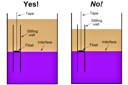
Another drawback with inductively coupled wire-guided floats is that they can be prone to ‘tape hang-ups’. This can occur when material builds up on the guide-wire which then hinders the movement of the float. This problem would become worse with viscous material measurement.

Components of inductively coupled wire-guided float systems are prone to accelerated wear because of continuous movement of the drive mechanism that is connected to the float on the liquid surface. Therefore the level of reliability of this method can be potentially poor.

Industry experts have spoken to suggest that this method of tank gauging should no longer be used because of the varying levels of reliability and accuracy of measurement, and the method’s high maintenance demands.

Float systems are becoming less commonplace mainly because the evolution of the other methods has advanced further than this method. Over time, as these systems break down, many fuel storage facilities are choosing to replace this type of system with different technology.

Read Next:

  • Thermal Differential Level Sensors
  • Level Switches for Storage Tanks
  • Capacitance Level Sensor Principle
  • Magnetostrictive Level Sensors
  • Types of Industrial Level Sensors
Don't Miss Our Updates
Be the first to get exclusive content straight to your email.
We promise not to spam you. You can unsubscribe at any time.
Invalid email address
You've successfully subscribed !

Recommended Articles

Magnetostrictive Level Transmitter Calibration Procedure
Tilt Level Switch Working Principle
Hydrostatic Tank Gauging (HTG)
Ultrasonic Level Transmitter Working Principle
Ultrasonic Level Transmitter Principle, Limitations, Calibration and configuration
Capacitance Level Sensor Principle, Limitations, Installation & Calibration
Share This Article
Facebook Whatsapp Whatsapp LinkedIn Copy Link
Share
Leave a Comment

Leave a Reply Cancel reply

Your email address will not be published. Required fields are marked *

Stay Connected

128.3kFollowersLike
69.1kFollowersFollow
208kSubscribersSubscribe
38kFollowersFollow

Categories

Recent Comments

  • William Snyder on Top Non-PLC Certification Courses for Automation Professionals
  • Kamli on Top Free PLC Software
  • Guifty Shimica on Top Non-PLC Certification Courses for Automation Professionals
  • Guifty Shimica on Top Non-PLC Certification Courses for Automation Professionals

Related Articles

Ultrasonic-Level-Transmitter-Animation

Ultrasonic Level Transmitter Animation

Closed Tank Level Measurement Formula

Siemens Differential Pressure Transmitter Calculations (Flange Type)

Drum Level Compensation of DP Transmitter

Drum Level Compensation and Range Calculation of DP Transmitter

remote seal capillary type dp transmitter

Closed Tank Remote Seal Capillary type DP Transmitter

Weight-based Level Instruments Principle

Weight-based Level Measurement Principle

DP-Level-Transmitter-Open-tank-calibration

Open Tank DP Level Transmitter Calibration

Closed Tank Level Measurement using DP Transmitter

How can we use a DP Flow Transmitter for Level Measurement

Conductive Level Measurement Working Principle

Conductive Level Measurement Working Principle

More Articles

Electrical Machines Questions and Answers

Synchronous Machines Distributed Winding Quiz

HART Communication Tutorial 1

HART Communication Tutorial Part 4

Difference between Current Transformer and Potential Transformer

Difference between Current Transformer and Potential Transformer

Plug Valve Parts

What is Plug Valve ?

What is Transparent Solar Panel

What is Transparent Solar Panel? – Working Principle and Theory

Junction Box Wiring

4-20mA Junction Box versus Fieldbus (FF) Junction Box

Turbine Flow Meter

All About Turbine Meters

Polyvinyl Alcohol in Oil Field

Polyvinyl Alcohol in Oil Field

Follow US
All rights reserved. Reproduction in whole or in part without written permission is prohibited.
Welcome Back!

Sign in to your account

Username or Email Address
Password

Lost your password?