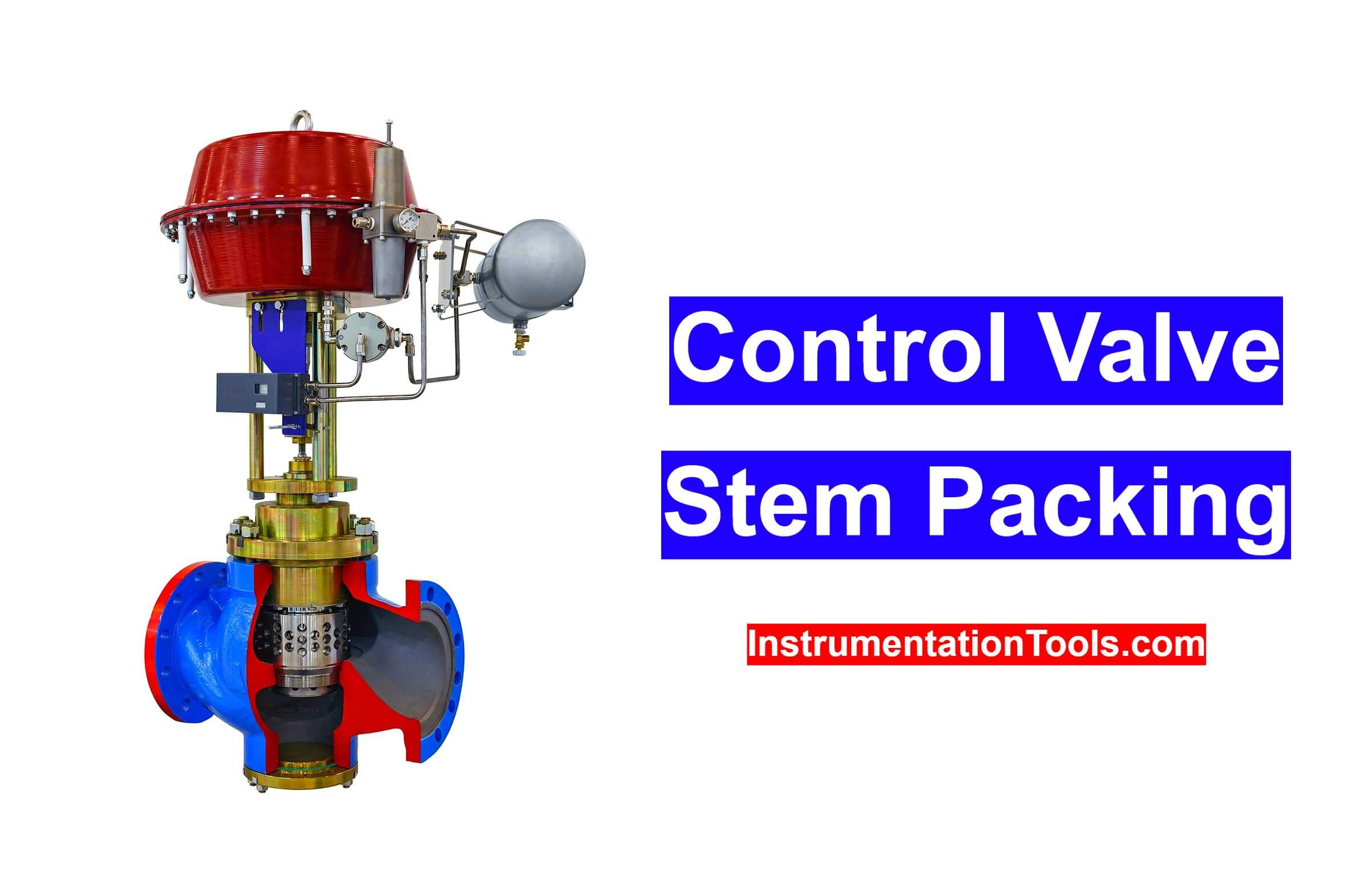
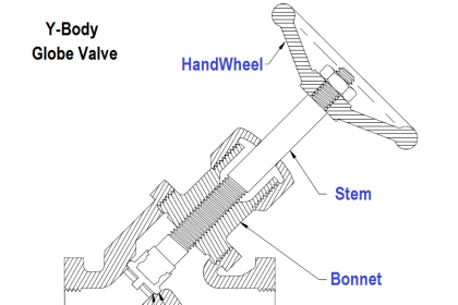
Stem packing is a type of seal, damps leakage between moving part and housing, is essential for the control valve.
Control Valve Stem Packing
There are few main criteria for the selection of valve packing.
They are
- Chemical resistance,
- Stem movement (speed),
- Pressure in the flow system,
- Medium temperature.
Replacement Procedure for Valve Stem Packing
The stem packing should be replaced preferably every 2 to 3 years even though valves have no failure such as leakage.
It is required to reduce valve operating torque and to prevent stem wear.
First of all, the correct selection of packing materials is confirmed, so that stem packing is suitable for the maximum working pressure and temperature of the process and the kind of fluid being handled.
Selection of a proper tool to take out the packing so as not to damage like scratches on the valve stem and valve packing chamber or stuffing box.
Clean the valve stem and valve packing chamber properly and carefully from the formation of scratches.
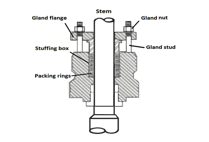
In general, the packing should be as thick as half the difference between the valve stem diameter and the interior diameter of the packing chamber or stuffing box. If no such packing is available, slightly thicker packing will do, but thinner packing is not suggested under any circumstances.
Preferably, with a sharp cutting device or packing cutter, cut the selected packing with a 30 degree to 40-degree at an inclined angle. The length of each piece of packing must be sized properly so that both ends may meet one another with the proper, correct dimension.
Dos and Don’ts
Inspection of the stuffing box and the stem is important because both should be clean from burrs, pitting, scoring, or corrosion on its surface.
Loading all pieces of packing at a time is not advised. Load the packing to half the death of the packing chamber, and press them down once. Then load the remaining pieces of packing and tighten them securely.
All gland packing should be located so that the seams are 120 degrees apart from each other. This will place the seam of the fourth packing ring position in the same vertical orientation as the first one.
Gland packing should not be tightened totally once for all, it is usually tightened to a position 3 to 4mm (1/8’’) below the top end of the packing chamber. If any leakage is found, tighten the packing further down till leakage stops.
How to Remove Stem Packing?
It is very hard in taking out or removing a gland packing can be very difficult sometimes, particularly if it is old and well set, it is necessary to have specially contoured tools.
There are also gland packing extractors available in the market, which are flexible and can be pulled out old packing smoothly.
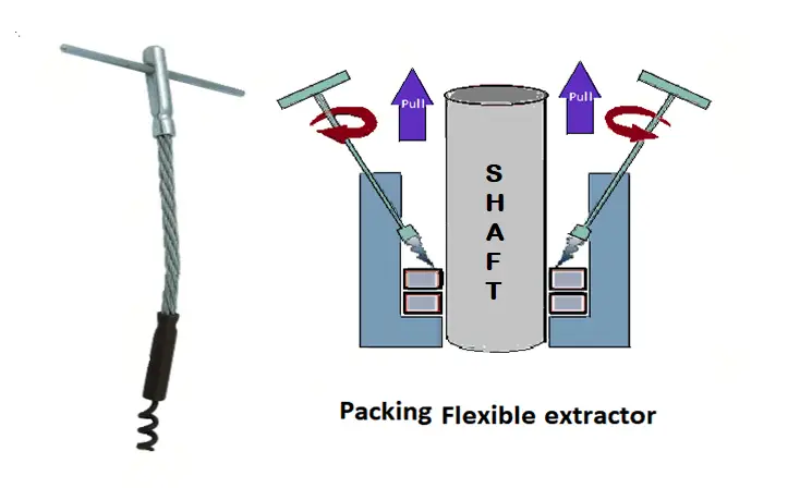
They just have to be twisted with the special tool to get a grip and then the packing can be pulled out. The problem comes when the old packing has lost its properties and the packing comes out in fibers.
Insert a stiff wire to measure the length of the valve bonnet. Measure the inner diameter of the bonnet and the outer diameter of the stem.
Suggest these two measurements and divide them by two. This is the packing thickness. Divide the depth of the packing chamber by the packing thickness to get the number of packing rings required.
Reference: The Valve Primer by Brent T Stojkov.
If you liked this article, then please subscribe to our YouTube Channel for Instrumentation, Electrical, PLC, and SCADA video tutorials.
You can also follow us on Facebook and Twitter to receive daily updates.
Read Next:


very good information sir thank you