Inst ToolsInst ToolsInst Tools
  • Courses
  • Automation
    • PLC
    • Control System
    • Safety System
    • Communication
    • Fire & Gas System
  • Instrumentation
    • Design
    • Pressure
    • Temperature
    • Flow
    • Level
    • Vibration
    • Analyzer
    • Control Valve
    • Switch
    • Calibration
    • Erection & Commissioning
  • Interview
    • Instrumentation
    • Electrical
    • Electronics
    • Practical
  • Q&A
    • Instrumentation
    • Control System
    • Electrical
    • Electronics
    • Analog Electronics
    • Digital Electronics
    • Power Electronics
    • Microprocessor
  • Request
Search
  • Books
  • Software
  • Projects
  • Process
  • Tools
  • Basics
  • Formula
  • Power Plant
  • Root Cause Analysis
  • Electrical Basics
  • Animation
  • Standards
  • 4-20 mA Course
  • Siemens PLC Course
Reading: How to Find LRV and URV of Closed Tank DP Level Transmitter
Share
Notification Show More
Font ResizerAa
Inst ToolsInst Tools
Font ResizerAa
  • Courses
  • Design
  • PLC
  • Interview
  • Control System
Search
  • Courses
  • Automation
    • PLC
    • Control System
    • Safety System
    • Communication
    • Fire & Gas System
  • Instrumentation
    • Design
    • Pressure
    • Temperature
    • Flow
    • Level
    • Vibration
    • Analyzer
    • Control Valve
    • Switch
    • Calibration
    • Erection & Commissioning
  • Interview
    • Instrumentation
    • Electrical
    • Electronics
    • Practical
  • Q&A
    • Instrumentation
    • Control System
    • Electrical
    • Electronics
    • Analog Electronics
    • Digital Electronics
    • Power Electronics
    • Microprocessor
  • Request
Follow US
All rights reserved. Reproduction in whole or in part without written permission is prohibited.
Inst Tools > Blog > Level Measurement > How to Find LRV and URV of Closed Tank DP Level Transmitter

How to Find LRV and URV of Closed Tank DP Level Transmitter

Last updated: January 5, 2020 10:53 pm
Editorial Staff
Level Measurement
2 Comments
Share
4 Min Read
SHARE

Find out the configuration of Lower Range Value (LRV) and Upper Range Value (URV) of a Differential Pressure (DP) Level Transmitter. Every DP transmitter needs to be configured using a HART communicator.

Contents
As we are using S.G which means comparing the density with that of water and the height is in inches. Hence when we multiply the two we get the answer in Inches of water column (no matter what the fluid is answer will be in inH2O ).At 4 mA Condition (LRV)At 20 mA Condition (URV)

Now let us see the formula for calculating the LRV and URV of the transmitter.

This formula needs two values only

S.G – (Specific gravity which has no unit so no tension of compatible units, if the process has given you density it can easily be converted into SG )

Length – All lengths must be entered in the formula as INCHES only !!

The Formula is Pressure(Head) = Specific Gravity * Height

and TADA !! you have answer in inH2O !!

As we are using S.G which means comparing the density with that of water and the height is in inches. Hence when we multiply the two we get the answer in Inches of water column (no matter what the fluid is answer will be in inH2O ).

LRV and URV of Closed Tank DP Level Transmitter

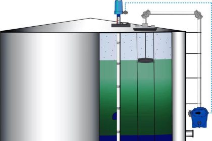
Given:- The C to C Distance is 1000 inches. (center to center)

The Transmitter is 50 inches below lower taping

At 4 mA Condition (LRV)

HP = “ 0.5 * 0 (As at 4 mA no liquid is inside the tank) “ +  0.5 * 50 inches (as transmitter is 50 inches below nozzle)

HP=25 Inches of Water Column is the pressure experienced at HP tap

LP  = “ 0.5 * 1000 (As the wet leg impulse line is fill with fluid ) “ + 0.5 * 50inches (as transmitter is 50 inches below nozzle)

LP = 500+25=525 Inches of Water Column is the pressure experienced at LP tap

Output =HP-LP= 25-525=-500 inches of water column must be calibrated for 4 mA

Therefore 4mA =(-500) InWC

so, lower range value (LRV) to be configured in Transmitter is -500 InWC

At 20 mA Condition (URV)

Closed Tank DP Level Transmitter

HP =  0.5 * 1000 (As at 20 mA liquid will be filled in the entire range) +

0.5 * 50inches (as the transmitter is 50 inches below nozzle)

HP= 500+25=525 Inches of Water Column is the pressure experienced at HP tap

LP = “ 0.5 * 1000 (As the wet leg impulse line is filled with fluid inside the tank ) “  +

0.5 * 50inches (as the transmitter is 50 inches below nozzle)

LP = 500+25=525 Inches of Water Column is the pressure experienced at LP tap

Output = HP-LP=525-525=-0 inches of water column must be calibrated for 20 mA

Therefore 20mA = 0 InWC

so, upper range value (URV) to be configured in the Transmitter is 0 InWC

The calibration Range will be -500 to 0 inches of the water column.

REFERENCE:- This above formula is taken from Emerson and to date I have found this to be the easiest and simplified literature explaining the level calculation.

Author: Asad Shaikh

Profile: Linkedin

Read Also:

  • Interface Level Calculation
  • Dry Leg & Wet Leg Calculation
  • Suppression and Elevation
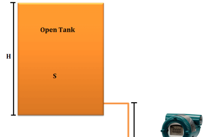
  • Open Tank Level Measurement
  • Closed tank Density Measurement
  • DP Transmitter Static Pressure Limit
  • Level Transmitter Auto Calibration
Don't Miss Our Updates
Be the first to get exclusive content straight to your email.
We promise not to spam you. You can unsubscribe at any time.
Invalid email address
You've successfully subscribed !

Continue Reading

Effect of Temperature & Pressure on Level Measurement
All About Instrumentation Impulse Lines
Displacer Level Transmitter Dry Calibration with Weights
Manual Level Measurement
Which Instrument is at Fault in this System?
Remote Seal Differential Pressure Transmitters Principle
Share This Article
Facebook Whatsapp Whatsapp LinkedIn Copy Link
Share
2 Comments
  • Moiz Amjad says:
    April 11, 2020 at 12:35 am

    I consider above mentioned calibration is wrong from my point of view it would be clike this as given below
    LRV= 0.5 *50 = 25 INH2O
    URV=0.5*1050= 525 INH2O
    SPAN=500 INH2O

    Reply
    • Régis says:
      November 16, 2022 at 7:07 pm

      C’est juste c’est plutôt votre calcul qui est faux. Appliqué la formulation de la pression hydraustatique

      Reply

Leave a Reply Cancel reply

Your email address will not be published. Required fields are marked *

Stay Connected

128.3kFollowersLike
69.1kFollowersFollow
210kSubscribersSubscribe
38kFollowersFollow

Categories

Explore More

Capacitance Level Measurement Working Principle
Displacer Level Sensor Working Animation
Magnetic Float Level Transmitter Working Principle
Basics of Level Measurement
Non Contact RADAR Level Transmitter Principle, Limitations, Design, Installation and Calibration
RF Capacitance Level Switch Working Principle
What is Thermal Differential Level Measurement?
Ultrasonic Level Switch Working Principle

Keep Learning

DP Level Measurement Problems

DP Level Measurement Problems

potentiometric level measurement principle

Potentiometric Level Measurement Principle

Open-Tank-DP-Level-Transmitter-with-Zero-Suppression-Calibration

DP Level Transmitter with Zero Suppression Calibration

Magnetostrictive Level Transmitter Calibration

Magnetostrictive Level Transmitter Calibration Procedure

Radiation Level Measurement Principle

Radiation Level Measurement

Capacitive Tank Gauges

Capacitive Tank Gauges

Contact and Non-Contact Level Sensors

Contact and Non-Contact Level Sensors

Level Gauge Interface Measurement

Level Gauge Interface & Temperature Problems

Learn More

How Could FB and FC Make Me Professional PLC Programmer

How Could FB and FC Make Me Professional PLC Programmer?

Pneumatic Moment-balance Differential Pressure Transmitter

Pneumatic Moment-balance Differential Pressure Transmitter

PLC Program for Alarm Indication in Process

PLC Program for Alarm Indication in Process Control

Squirrel Cage Induction Motor Synchronous View

Squirrel Cage Induction Motor Animation

Flow Meter Calibration Procedure

Flow Meter Calibration

why-reactive-power-is-generated-at-load

Why Reactive Power is Generated at Load

Fire-Triangle-in-Gas-Detection-System

Basics of Fire Detection System

Analog Electronics Objective Questions

Analog Electronics Objective Questions – Set 2

Menu

  • About
  • Privacy Policy
  • Copyright

Quick Links

  • Learn PLC
  • Helping Hand
  • Part Time Job

YouTube Subscribe

Follow US
All rights reserved. Reproduction in whole or in part without written permission is prohibited.
Welcome Back!

Sign in to your account

Username or Email Address
Password

Lost your password?