Inst ToolsInst ToolsInst Tools
  • Courses
  • Automation
    • PLC
    • Control System
    • Safety System
    • Communication
    • Fire & Gas System
  • Instrumentation
    • Design
    • Pressure
    • Temperature
    • Flow
    • Level
    • Vibration
    • Analyzer
    • Control Valve
    • Switch
    • Calibration
    • Erection & Commissioning
  • Interview
    • Instrumentation
    • Electrical
    • Electronics
    • Practical
  • Q&A
    • Instrumentation
    • Control System
    • Electrical
    • Electronics
    • Analog Electronics
    • Digital Electronics
    • Power Electronics
    • Microprocessor
  • Request
Search
  • Books
  • Software
  • Projects
  • Process
  • Tools
  • Basics
  • Formula
  • Power Plant
  • Root Cause Analysis
  • Electrical Basics
  • Animation
  • Standards
  • 4-20 mA Course
  • Siemens PLC Course
Reading: Series and Parallel Inductors
Share
Font ResizerAa
Inst ToolsInst Tools
Font ResizerAa
  • Courses
  • Design
  • PLC
  • Interview
  • Control System
Search
  • Courses
  • Automation
    • PLC
    • Control System
    • Safety System
    • Communication
    • Fire & Gas System
  • Instrumentation
    • Design
    • Pressure
    • Temperature
    • Flow
    • Level
    • Vibration
    • Analyzer
    • Control Valve
    • Switch
    • Calibration
    • Erection & Commissioning
  • Interview
    • Instrumentation
    • Electrical
    • Electronics
    • Practical
  • Q&A
    • Instrumentation
    • Control System
    • Electrical
    • Electronics
    • Analog Electronics
    • Digital Electronics
    • Power Electronics
    • Microprocessor
  • Request
Follow US
All rights reserved. Reproduction in whole or in part without written permission is prohibited.
Inst Tools > Blog > Electrical Theory > Series and Parallel Inductors

Series and Parallel Inductors

Last updated: July 26, 2018 1:29 pm
Editorial Staff
Electrical Theory
1 Comment
Share
1 Min Read
SHARE

Inductors in Series

Inductors in series are combined like resistors in series as shown in below figure.

Inductors in Series

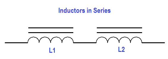
Figure 4 : Inductors in Series

Equivalent inductance (Leq ) of two inductors in series (Figure 4) is given by below Equation.

Leq =L1 +L2 + … Ln

Inductors in parallel

Inductors in parallel are combined like resistors in parallel as shown in below figure.

Inductors in parallel

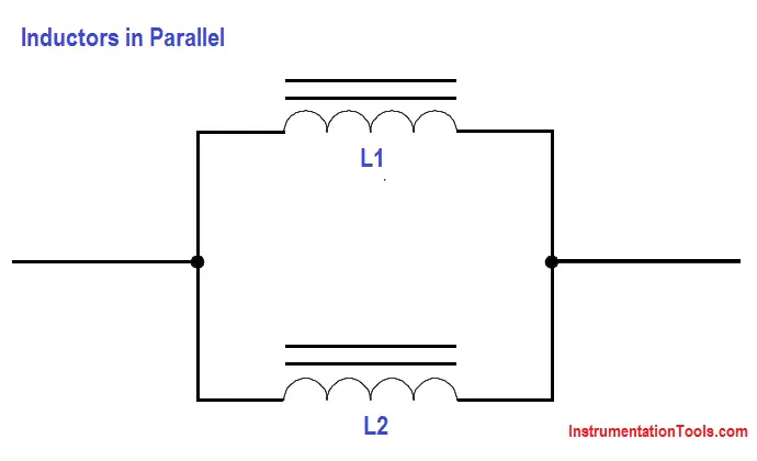
Figure 5 : Inductors in Parallel

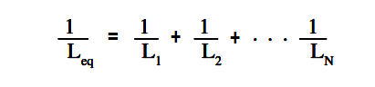
The equation for parallel inductors is

Inductors in parallel Equation

When only two inductors are in parallel, as shown in Figure 5, The above Equation may be simplified as given in below Equation.

Parallel Inductors Formula

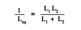
The above Equation is valid when there are only two inductors in parallel.

Don't Miss Our Updates
Be the first to get exclusive content straight to your email.
We promise not to spam you. You can unsubscribe at any time.
Invalid email address
You've successfully subscribed !

Continue Reading

DC Motor Connections
Starting a Synchronous Motor
Power Factor
Series Resistance
Capacitance
Shunt-Wound DC Generators
Share This Article
Facebook Whatsapp Whatsapp LinkedIn Copy Link
Share
1 Comment
  • Nasi says:
    June 1, 2023 at 2:14 pm

    Hi. Thank you so much for the information.

    Reply

Leave a Reply Cancel reply

Your email address will not be published. Required fields are marked *

Stay Connected

128.3kFollowersLike
69.1kFollowersFollow
210kSubscribersSubscribe
38kFollowersFollow

Categories

Explore More

Transformer Current Ratio
Transformer Impedance Ratio
Rectifiers, Forward Bias and Reverse Bias
Voltage and Current Phase Relationships in an Inductive Circuit
DC Machines Terminology
Three Phase Systems
Calculate Power in Parallel RL Circuit
Transformer Operation Under No-Load

Keep Learning

DC Circuit Node Equations

DC Circuit Analysis Node Equations

Parallel Circuit Unknown Resistance

Simplified Formulas for Parallel Circuit Resistance Calculations

current division Formula for Resistor Circuit

Current Division

AC Generator Operation

Losses in AC Generator

Compounded DC Generator

Parallel AC Generators

Current in a Capacitor

Capacitance and Capacitive Reactance

Batteries Connected in Parallel

Battery Operation : Series and Parallel

Wiring Diagram

Wiring Diagram

Learn More

Emergency Block Valve

SIS Emergency Block Valves (EBV)

diode-basic-structure-symbol

Forward Bias & Reverse Bias of a Diode

PLC Conveyor Forward and Reverse Logic

Advanced PLC Conveyor Control: Forward and Reverse Rotation

Incident Investigation: Motor Operated Valve Lesson

Incident Investigation: Motor Operated Valve Lesson

Fixed Gas Detectors vs. Portable Gas Detectors

Fixed Gas Detectors vs. Portable Gas Detectors

schottky diode working principle

Schottky Diode Working Principle

Industrial Automation Architecture reference model

Industrial Automation System Architecture Reference Model

Air Lock Relay Working Principle

Control Valve Air Lock Relay Working Principle

Menu

  • About
  • Privacy Policy
  • Copyright

Quick Links

  • Learn PLC
  • Helping Hand
  • Part Time Job

YouTube Subscribe

Follow US
All rights reserved. Reproduction in whole or in part without written permission is prohibited.
Welcome Back!

Sign in to your account

Username or Email Address
Password

Lost your password?