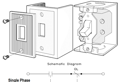
Inst ToolsInst ToolsInst Tools
  • Ask
  • Courses
  • Videos
  • Q & A
    • Interview
      • Instrumentation
      • Electronics
      • Electrical
      • Practical Questions
    • MCQ
      • Instrumentation MCQ
      • Electrical MCQ
      • Electronics MCQ
      • Control Systems MCQ
      • Analog Electronics MCQ
      • Digital Electronics MCQ
      • Power Electronics MCQ
      • Microprocessor MCQ
      • Multiple Choice Questions
  • EE
    • Electronics
      • Electronics Q & A
      • Electronic Basics
      • Electronic Devices & Circuits
      • Electronics Animation
      • Digital Electronics
    • Electrical
      • Electrical Basics
      • Electrical Q & A
      • Power Electronics
      • Electrical Machines
      • Electrical Animation
      • Power Systems
      • Switchgear & Protection
      • Transmission & Distribution
  • Measure
    • Control Valves
    • Calibration
    • Temperature
    • Pressure
    • Flow
    • Level
    • Analyzers
    • Switches
    • Vibration
    • Solenoid Valve
  • Control
    • PLC Tutorials
    • Control Systems
    • Safety Instrumented System (SIS)
    • Communication
    • Fire & Gas System
  • More
    • Design
    • Tools
    • Animation
    • Basics
    • Formulas
    • Standards
    • TextBooks
    • Common
    • Software
    • Excel Tools
    • Erection & Commissioning
    • Process Fundamentals
    • Videos
    • Books
Search
All rights reserved. Reproduction in whole or in part without written permission is prohibited.
Reading: Rectifiers, Forward Bias and Reverse Bias
Share
Notification Show More
Font ResizerAa
Inst ToolsInst Tools
Font ResizerAa
  • Courses
  • PLC Tutorials
  • Control Systems
Search
  • Ask
  • Courses
  • Videos
  • Q & A
    • Interview
    • MCQ
  • EE
    • Electronics
    • Electrical
  • Measure
    • Control Valves
    • Calibration
    • Temperature
    • Pressure
    • Flow
    • Level
    • Analyzers
    • Switches
    • Vibration
    • Solenoid Valve
  • Control
    • PLC Tutorials
    • Control Systems
    • Safety Instrumented System (SIS)
    • Communication
    • Fire & Gas System
  • More
    • Design
    • Tools
    • Animation
    • Basics
    • Formulas
    • Standards
    • TextBooks
    • Common
    • Software
    • Excel Tools
    • Erection & Commissioning
    • Process Fundamentals
    • Videos
    • Books
Follow US
All rights reserved. Reproduction in whole or in part without written permission is prohibited.
Inst Tools > Blog > Electrical Theory > Rectifiers, Forward Bias and Reverse Bias

Rectifiers, Forward Bias and Reverse Bias

Last updated: July 22, 2018 10:16 pm
Editorial Staff
Electrical Theory
No Comments
Share
3 Min Read
SHARE

Rectifiers

Most electrical power generating stations produce alternating current. The major reason for generating AC is that it can be transferred over long distances with fewer losses than DC; however, many of the devices which are used today operate only, or more efficiently, with DC. For example, transistors, electron tubes, and certain electronic control devices require DC for operation. If we are to operate these devices from ordinary AC outlet receptacles, they must be equipped with rectifier units to convert AC to DC. In order to accomplish this conversion, we use diodes in rectifier circuits.

Contents
RectifiersForward BiasReverse Bias

The purpose of a rectifier circuit is to convert AC power to DC. The most common type of solid state diode rectifier is made of silicon. The diode acts as a gate, which allows current to pass in one direction and blocks current in the other direction. The polarity of the applied voltage determines if the diode will conduct. The two polarities are known as forward bias and reverse bias.

Forward Bias

A diode is forward biased when the positive terminal of a voltage source is connected to its anode, and the negative terminal is connected to the cathode (Figure 4A). The power source’s positive side will tend to repel the holes in the p-type material toward the p-n junction by the negative side. A hole is a vacancy in the electron structure of a material. Holes behave as positive charges. As the holes and the electrons reach the p-n junction, some of them break through it (Figure 4B). Holes combine with electrons in the n-type material, and electrons combine with holes in the p-type material.

Forward Bias

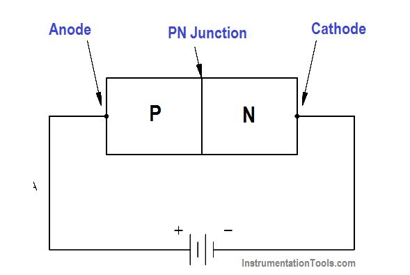
Figure 4 A – Forward-Biased Diode

Forward Bias Diode

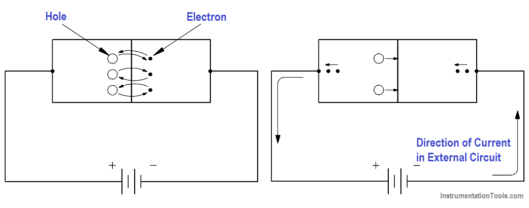
Figure 4B (Left) & 4C (Right)

When a hole combines with an electron, or an electron combines with a hole near the p-n junction, an electron from an electron-pair bond in the p-type material breaks its bond and enters the positive side of the source. Simultaneously, an electron from the negative side of the source enters the n-type material (Figure 4C). This produces a flow of electrons in the circuit.

Reverse Bias

Reverse biasing occurs when the diode’s anode is connected to the negative side of the source, and the cathode is connected to the positive side of the source (Figure 5A). Holes within the p-type material are attracted toward the negative terminal, and the electrons in the n-type material are attracted to the positive terminal (Figure 5B). This prevents the combination of electrons and holes near the p-n junction, and therefore causes a high resistance to current flow. This resistance prevents current flow through the circuit.

Reverse-Biased Diode

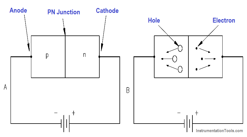
Figure 5 Reverse-Biased Diode

Don't Miss Our Updates
Be the first to get exclusive content straight to your email.
We promise not to spam you. You can unsubscribe at any time.
Invalid email address
You've successfully subscribed !
Applying Kirchhoff’s Current Law
Electrical Wiring Terminology
Parallel Circuit Current Calculations
Three Phase AC Generators
DC Circuit Analysis Node Equations
Share This Article
Facebook Whatsapp Whatsapp LinkedIn Copy Link
Share
Leave a Comment

Leave a Reply Cancel reply

Your email address will not be published. Required fields are marked *

Stay Connected

128.3kFollowersLike
69.1kFollowersFollow
208kSubscribersSubscribe
38kFollowersFollow

Categories

Recent Comments

  • Kamli on Top Free PLC Software
  • Guifty Shimica on Top Non-PLC Certification Courses for Automation Professionals
  • Guifty Shimica on Top Non-PLC Certification Courses for Automation Professionals
  • MIHARITSOA Aina Sitraka on Top Non-PLC Certification Courses for Automation Professionals

Related Articles

Shunt-Wound DC Motor

Shunt-Wound Motor Operation

Capacitor Principle

Capacitor

DC Generator

DC Generator

Transformer Efficiency and Loses Formula

Transformer Losses and Efficiency

Series Circuit

Series Circuit

Units of Electrical Measurement

Units of Electrical Measurement

Inductor Principle

Inductance and Inductive Reactance

Transformer voltage and turns ratio

Transformer Voltage Ratio

More Articles

High Integrity Pressure Protection System HIPPS

Overview of HIPPS System

Programmable Logic Controllers Multiple Choice Questions

Programmable Logic Controllers Multiple Choice Questions

Introduction to PLC

#9 PLC Best Practices – Validate indirections

Optical Pyrometer

Optical Pyrometer Working Principle

Preventa XPS MC, XPS MP - Safety controllers

High-end Programmable Logic Controller – Schneider PLC

VFD Interview Questions and Answers

VFD Interview Questions and Answers – Electrical Drives

Vortex Flow GIF

Working Principle of Vortex Flow Meter

Silicon-Controlled Rectifier (SCR)

Introduction to Thyristor – History, Types, Principle, Advantages

Follow US
All rights reserved. Reproduction in whole or in part without written permission is prohibited.
Welcome Back!

Sign in to your account

Username or Email Address
Password

Lost your password?