Measurement principle
The capacitive measuring principle is based on the method of the operation of a capacitor.
A capacitor is formed by two differently charged electrodes isolated from each other. Applying an alternating current between the electrodes will create an electric field. This electrical field depends on the distance between the electrodes, the size of electrodes surface, and the isolating medium between the electrodes.
If the distance between electrodes and size of surface of the electrodes are kept constant, only the medium would have an effect on the electrical capacitance. When the medium change the electrical field changes also consequently the capacitance evolves as follows:
- Capacitance (C) = Dielectric constant (Ɛ0) × Relative Dielectric constant (DC) × Electrode Surface Area Where the dielectric constant (Ɛ0) is the electric field constant (Ɛ0 = 8.8 × 10‐12 C/(Vm).
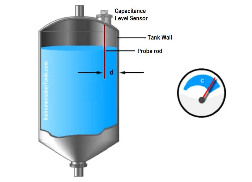
Figure – Capacitance measurement principle
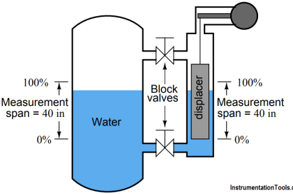
Media with a low dielectric constant (DC value) cause very small changes of the capacitance value in level measurement while media with a high DC value produce respectively large capacitance changes. In many interface applications, the medium with the lower DC value is on top, e. g. hydrocarbon (DC = 2) on water (DC = 80).
The upper medium provides only a minimum contribution to the overall capacitance value – only the water level (the interface layer) is thus indicated as level.
In order to make use of this effect, the DC value of the two media should be sufficiently different from each other.
Usually a medium with a low DC value is non‐conductive while a medium with a high DC value is conductive. Therefore interface measurement with a non‐conductive and a conductive medium is always possible.
Limitations
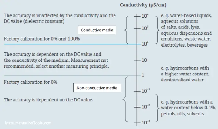
Figure – Capacitance operating range
If a process coats or fouls a capacitance probe, a compensation option may be required to prevent false highlevel readings.
Continuous level capacitance transmitters require that the liquid being measured remains at a constant dielectric value. If this is not the case, the transmitter should have the capability to compensate for the liquid dielectric variation.
Probes mounted directly in the vessel typically cannot be replaced with the process in service unless they are mounted in a sensor cage with isolation valves.
The rod probes require sufficient height clearance, depending on the length of the probe.
It cannot measure liquids which have a viscosity above 2000 cst.
Selection
The capacitive level measurement can be used in aggressive media when a fully coated probe (e.g. PTFE) is used.
Capacitive measurement has a very fast response time which makes it ideal for processes with fast level changes and small containers.
The measurement principle is not affected by the density variation of the media.
For interface measurements a conductive and non‐conductive media is required.
At this interface the difference between the conductivity of the conductive media should be greater than 100 μS/cm and the conductivity of the non‐conductive media should be lower than 1 μS/cm.
An oil‐water emulsion has all the conductivity range between 1 and 100 μS/cm depending on the oil‐water bubble repartition. This means that a capacitance probe will detect the media above 100 μS/cm (i.e. conductive media) and will not detect the emulsion layer (between 1 and 100 μS/cm) as well as the non-conductive media layer (i.e. <1 μS/cm).
Non‐conductive build‐up on the probe affects the measurement.
Design
The probes should be made of metallic, conductive electrode with full plastic insulation regardless of the conductivity of the medium.
When mounted, a good electrically conductive connection between the process connection and the tank should be ensured. An electrically conductive sealing band can be used.
Rod probes with a ground tube should be used in the event of severe lateral loads.
The length of the probe should be designed in accordance with level measurement range.
Installation
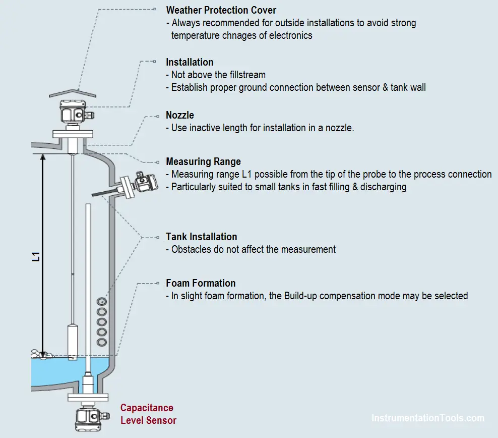
Figure – Capacitance Level Sensor installation
The vessel earthing (grounding) method, which can be critical to the operation of the device, should be assessed.
Calibration and configuration
Capacitance probes are calibrated at the factory for media with a conductivity ≥100 μS/cm (e.g. for all waterbased liquids, acids, alkalis…).
A site calibration is only necessary if the 0%‐value or the 100%‐value should be adjusted to suit specific measurement requirements (e.g. tank/capacitance distance <250 mm, conductivity <100 μS/cm or specific range).
A distinction is generally made between two types of calibration:
- Wet calibration: The probe can be calibrated for its full range i.e. lower level (0% level calibration) and high level (100% level). Other intermediate values can also be performed.
- Dry calibration: The level capacitance can be simulated by entering the low and high level values. Capacitance units will calculate automatically the capacitance variation image based in the factory calibration for a conductivity ≥100 μS/cm.
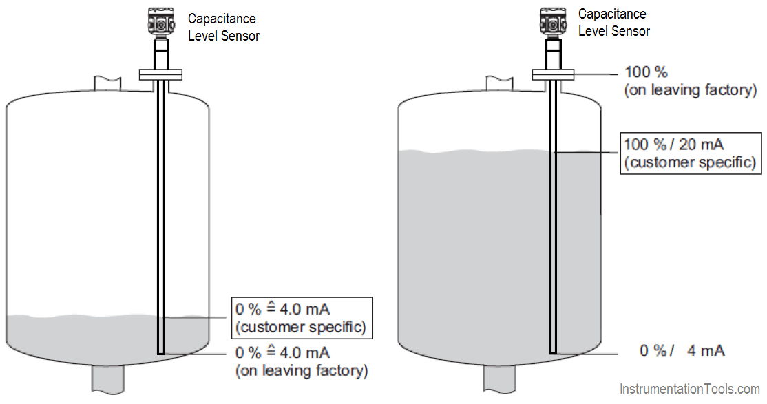
Figure – Capacitance Level Sensor calibration
Source : International Association of Oil & Gas Producers
Acknowledgements : IOGP Instrumentation and Automaton Standards Subcommittee (IASSC), BG Group, BP, Endress + Hauser, Emerson, Honeywell, Krohne, Petrobras, PETRONAS Carigali Sdn Bhd, Repsol, Siemens, Statoil, Total, Vega, Yokogawa.