Create a PLC program for alarm indication in the process control industry. Learn the PLC programming with this industrial example.
Alarm Indication in Process Control
In many industries there are lots of machines which are performing many tasks automatically. There are many sensors and components used in system or process.
Sometimes operator may not be identify the problems of machine or system by visual observations. And also sometimes there will be a chance that machine stops working due to some problem in it.
Problem Diagram

PLC Solution
We can solve this problem by adding alarms in system or process. Alarms are added to alert operator to monitor that machine/process about to cross its limit values or already crossed the limit.
Alarms are indicated to the operator by annunciator or horns, and lights of different colors on the panel. (For example, green lights meant OK, Yellow meant not OK, and Red meant BAD.)
The purpose of alarms is to use automation to help human operators as they monitor and control processes, and alert them regarding abnormal situations of the plant.
Incoming/Input process signals are continuously monitored, and if the value of a given signal moves into an abnormal condition, a visual and/or audio alarm informs the operator regarding the situation.
We can configure alarms for system by different ways, such as MIMIC, indication lamps on panel board, SCADA, HMI etc.
For our problem discussions, we considered one simple system and configure alarms for the system.
For example consider one filling and discharging process and in this system we want to consider some alarms, we will show alarm by using lamps on panel board.
For example, consider following alarms for our system,
- Emergency stop pressed
- Feed valve open error
- Feed valve close error
- Discharge valve open error
- Discharge valve close error
Here all are errors, so we take all red color indication as shown in above figure.
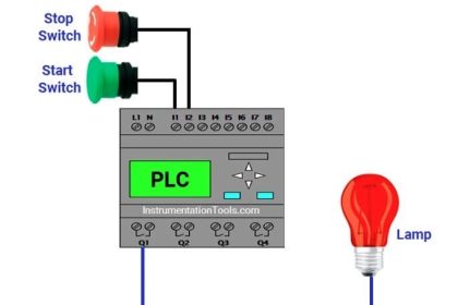
List of Inputs & Outputs in PLC
Inputs List
- Cycle START : I0.0
- Cycle STOP : I0.1
- Low Level Switch, LL : I0.2
- High Level Switch, LH : I0.3
- Feed VLV open LS : I0.4
- Feed VLV close LS : I0.5
- Disc. VLV open LS : I0.6
- Disc. VLV close LS : I0.7
- Emergency STOP : I1.0
- RESET : I1.1
Output List
- Cycle ON : Q0.0
- Feed valve : Q0.1
- Disc valve : Q0.2
- BUZZER : Q0.3
- Emergency STOP pressed : Q0.4 (Indication lamp)
- Feed VLV open error : Q0.5 (Indication lamp)
- Feed VLV close error : Q0.6 (Indication lamp)
- Disc VLV open error : Q0.7 (Indication lamp)
- Disc VLV close error : Q1.0 (Indication lamp)
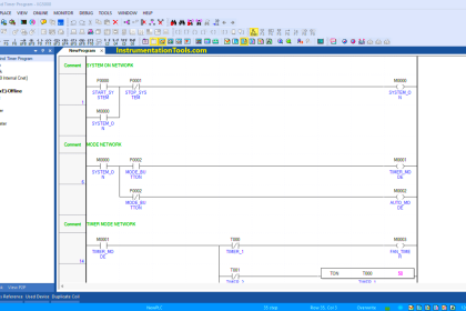
PLC Program for Alarm indication in Process Control
Logic Explained
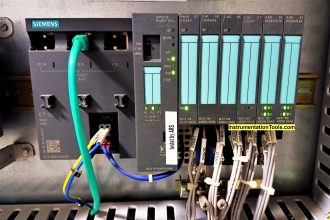
In this application, we have used Siemens S7-300 PLC and TIA Portal Software for programming.
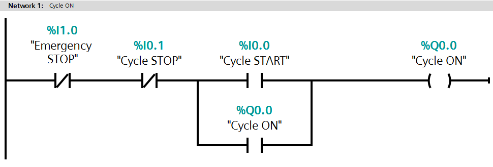
Network 1:
In network 1, we used latching circuit for cycle ON (Q0.0) output. It can be started by pressing cycle START PB (I0.0) and STOP by pressing STOP PB (I0.1).
When cycle will be START then system checks level of the tank. If tank level is low then the feeding process will start and if tank level reaches high then Discharge cycle will START.
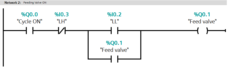
Network 2:
When tank reaches low level then LL (I0.2) will be activated and feeding cycle will be ON. Here we have taken NC contact of LH (I0.3) so when PLC will detect high level then it will STOP feeding cycle.
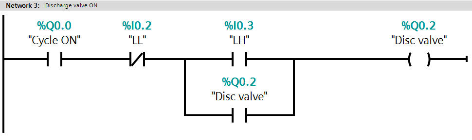
Network 3:
When tank reaches high level then LH (I0.3) will be activated and discharging cycle will be ON.
Here we have taken NC contact of LL (I0.2) so when PLC will detect low level then it will STOP discharge cycle.
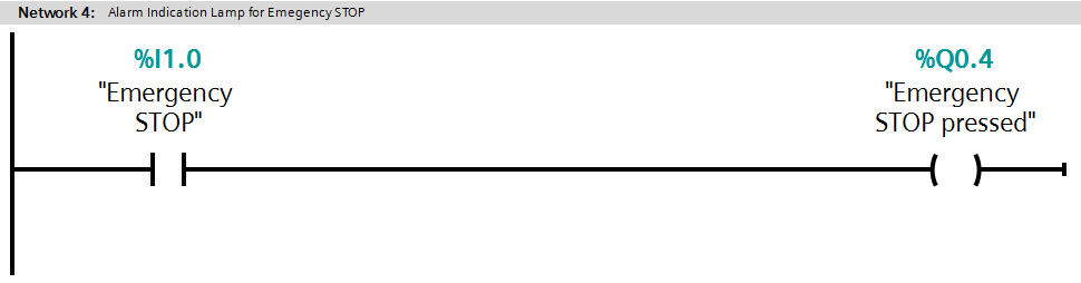
Network 4:
When system receives Emergency STOP (I1.0) input then it will activate the Emergency STOP pressed output (Q0.4) and alarm indication will be provided to the operator.
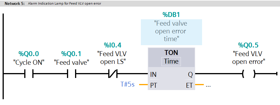
Network 5:
In this network we have configured feed VLV open error alarm (Q0.5), when feed valve is ON and Feed VLV open LS (I0.4) is not detected then timer will START and after 5s Feed VLV open error alarm is ON (Q0.5).
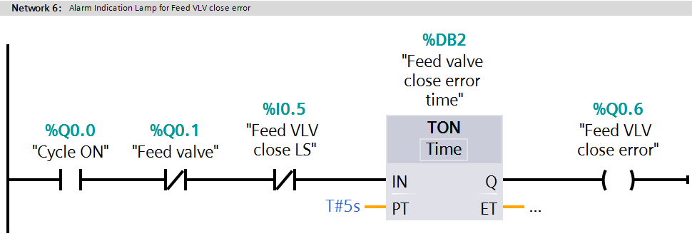
Network 6:
In this network we have configured feed VLV CLOSE error alarm (Q0.6), when feed valve is CLOSE and Feed VLV CLOSE LS (I0.5) is not detected then timer will START and after 5s Feed VLV CLOSE error alarm is ON (Q0.6).
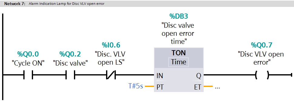
Network 7:
In this network we have configured Disc VLV OPEN error alarm (Q0.7), when disc valve is ON and disc VLV OPEN LS (I0.6) is not detected then timer will START and after 5s disc VLV OPEN error alarm is ON (Q0.7).
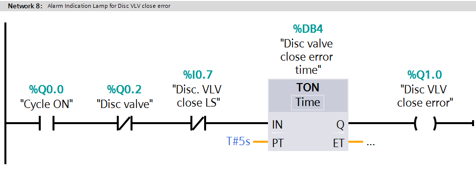
Network 8:
In this network we have configured Disc VLV CLOSE error alarm (Q1.0), when disc valve is CLOSE and disc VLV CLOSE LS (I0.7) is not detected then timer will start and after 5s disc VLV close error alarm is ON (Q1.0).
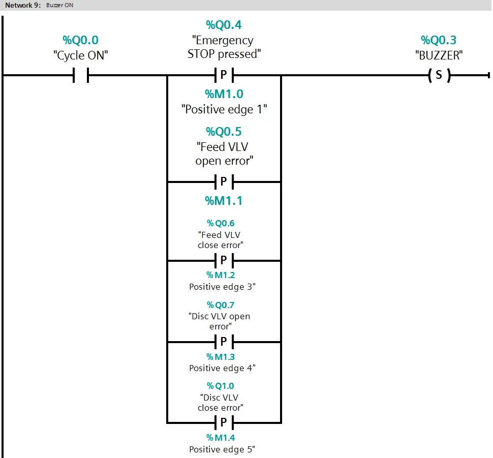
Network 9:
In this network we have configured BUZZER for all alarms, when alarm detected then BUZZER (Q0.3) will be activated and it can be RESET by pressing RESET (I1.1).
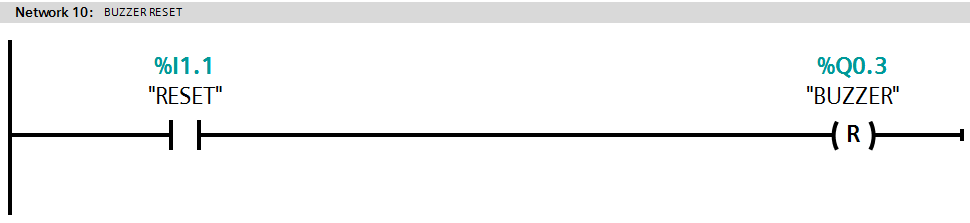
Network 10:
Operator can reset the BUZZER by pressing RESET (I1.0)
Test Cases

Note: The above PLC Logic provided for basic idea about application of PLC in Alarm Indication of a Process. The Logic is limited and not complete application.
Author: Bhavesh
If you liked this article, then please subscribe to our YouTube Channel for PLC and SCADA video tutorials.
You can also follow us on Facebook and Twitter to receive daily updates.
Read Next:
- Understanding PLC Ladder Logic
- Compare DCS, PLC, and RTU
- PLC Program for Flow Totalizer
- T Flip Flop PLC Ladder Diagram
- Fan Control Unit System for Industry


excellent information.
Many thanks for the article! Do you have any examples of Rockwell software ladder and supervisor? Thank you.
Good and very useful article. . worth reading. .
good article…tq