Inst ToolsInst ToolsInst Tools
  • Courses
  • Automation
    • PLC
    • Control System
    • Safety System
    • Communication
    • Fire & Gas System
  • Instrumentation
    • Design
    • Pressure
    • Temperature
    • Flow
    • Level
    • Vibration
    • Analyzer
    • Control Valve
    • Switch
    • Calibration
    • Erection & Commissioning
  • Interview
    • Instrumentation
    • Electrical
    • Electronics
    • Practical
  • Q&A
    • Instrumentation
    • Control System
    • Electrical
    • Electronics
    • Analog Electronics
    • Digital Electronics
    • Power Electronics
    • Microprocessor
  • Request
Search
  • Books
  • Software
  • Projects
  • Process
  • Tools
  • Basics
  • Formula
  • Power Plant
  • Root Cause Analysis
  • Electrical Basics
  • Animation
  • Standards
  • 4-20 mA Course
  • Siemens PLC Course
Reading: What is a Annunciator ?
Share
Notification Show More
Font ResizerAa
Inst ToolsInst Tools
Font ResizerAa
  • Courses
  • Design
  • PLC
  • Interview
  • Control System
Search
  • Courses
  • Automation
    • PLC
    • Control System
    • Safety System
    • Communication
    • Fire & Gas System
  • Instrumentation
    • Design
    • Pressure
    • Temperature
    • Flow
    • Level
    • Vibration
    • Analyzer
    • Control Valve
    • Switch
    • Calibration
    • Erection & Commissioning
  • Interview
    • Instrumentation
    • Electrical
    • Electronics
    • Practical
  • Q&A
    • Instrumentation
    • Control System
    • Electrical
    • Electronics
    • Analog Electronics
    • Digital Electronics
    • Power Electronics
    • Microprocessor
  • Request
Follow US
All rights reserved. Reproduction in whole or in part without written permission is prohibited.
Inst Tools > Blog > eBooks > What is a Annunciator ?

What is a Annunciator ?

Last updated: July 16, 2017 12:15 pm
Editorial Staff
eBooks
3 Comments
Share
4 Min Read
SHARE

Process alarm switches may be used to trigger a special type of indicator device known as an annunciator. An annunciator is an array of indicator lights and associated circuitry designed to secure a human operator’s attention by blinking and sounding an audible buzzer when a process changes into an abnormal state. The alarm state may be then “acknowledged” by an operator pushing a button, causing the alarm light to remain on (solid) rather than blink, and silencing the buzzer. The indicator light does not turn off until the actual alarm condition (the process alarm) has returned to its regular state.

This photograph shows an annunciator located on a control panel for a large engine-driven pump. Each white plastic square with writing on it is a translucent pane covering a small light bulb. When an alarm condition occurs, the respective light bulb flashes, causing the translucent white plastic to glow, highlighting to the operator which alarm is active:

Annunciators

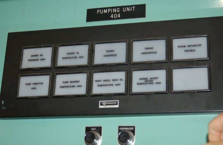
Note the two pushbutton switches below labeled “Test” and “Acknowledge.” Pressing the “Acknowledge” button will silence the audible buzzer and also turn any blinking alarm light into a steady (solid) alarm light until the alarm condition clears, at which time the light turns off completely. Pressing the “Test” button turns all alarm lights on, to ensure all light bulbs are still functional.

Opening the front panel of this annunciator reveals modular relay units controlling the blinking and acknowledgment latch functions, one for each alarm light:

Annunciators - 2

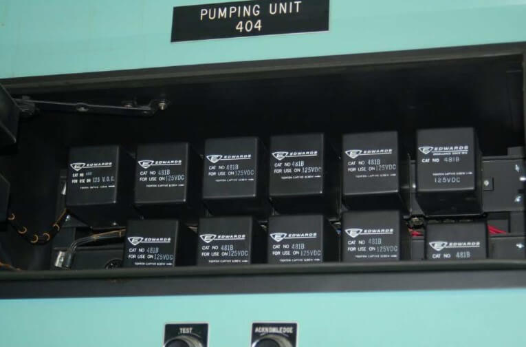
This modular design allows each alarm channel to be serviced without necessarily interrupting the function of the other channels in the annunciator panel.

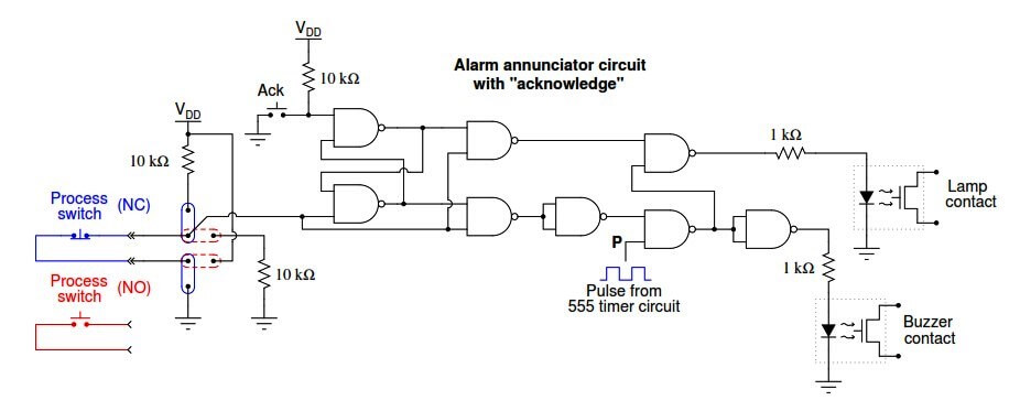
A simple logic gate circuit illustrates the acknowledgment latching feature (here implemented by an S-R latch circuit) common to all process alarm annunciators:

Annunciators Circuit

Panel-mounted annunciators are becoming a thing of the past, as computer-based alarm displays replace them with advanced capabilities such as time logging, first-event recording, and multiple layers of acknowledgment/access. Time logging is of particular importance in the process industries, as the sequence of events is often extremely important in investigations following an abnormal operating condition. Knowing what happened, and exactly when it happened is much more informative than simply knowing which alarms have tripped.

What is First Event ? :

When a complex machine or process with many shutdown sensors automatically shuts down, it may be difficult to discern after the fact which shutdown device was responsible. For instance, imagine an engine-powered generator automatically shutting down because one of the generator’s “trip” sensors detected an under-voltage condition. Once the engine shuts down, though, multiple trip sensors will show abnormal conditions simply because the engine is not running anymore.

The oil pressure sensor is one example of this: once the engine shuts down, there will no longer be any oil pressure, thus causing that alarm to activate. The under-voltage alarm falls into this category as well: once the engine shuts down, the generator will no longer be turning and therefore its output voltage must be zero. The problem for any human operator encountering the shut-down engine is that he or she cannot tell which of these alarms was the initiating cause of the shutdown versus which of these alarms simply activated after the fact once the engine shut off. An annunciator panel showing both an under-voltage and a low oil pressure light does not tell us which event happened first to shut down the generator. A “first-event” (sometimes called a “first-out”) annunciator, however, shows which trip sensor was the first to activate, thus revealing the initiating cause of the event.

Don't Miss Our Updates
Be the first to get exclusive content straight to your email.
We promise not to spam you. You can unsubscribe at any time.
Invalid email address
You've successfully subscribed !

Continue Reading

Tube and tube fittings
Basics of Limit switches
Fiber Optic Sensors
Introduction to Industrial Instrumentation
Signal Coupling and Cable Separation
Sanitary Pipe Fittings for the Instruments
Share This Article
Facebook Whatsapp Whatsapp LinkedIn Copy Link
Share
3 Comments
  • azetou says:
    August 27, 2017 at 10:30 am

    Hi , thanks for the article. I noticed in the first picture that there is an alarm for engine oil pressure “high”, where in practice we often set an alarm for engine oil pressure “low” to indicate that there is a problem in lubrication. any explanation for this ??

    Reply
    • S Bharadwaj Reddy says:
      August 27, 2017 at 10:38 am

      It depends on application and requirements. Learn the logic & principle. Here we are discussing some examples for our easy understanding.

      Reply
  • Fig says:
    August 27, 2017 at 11:11 am

    Are you talking about yourself?
    CR1 coil is not energized.
    Therefore the first relay which is NC, would still be closed and the blue light would be on as well.

    Reply

Leave a Reply Cancel reply

Your email address will not be published. Required fields are marked *

Stay Connected

128.3kFollowersLike
69.1kFollowersFollow
210kSubscribersSubscribe
38kFollowersFollow

Categories

Explore More

Electrical Signal and Control Wiring
What is Parallel Thread Pipe Fittings ?
Ultrasonic Level Switch Principle
Cable Routing
Fiber Optic Cable Connectors, Routing, and Safety
Basics of AC Induction Motors
Basics of Pressure switches
What is Flanged Pipe Fittings ?

Keep Learning

Transmitter Identification Codes

Instrument Identification Tags

National Pipe Thread Cross Sectional View

What is Tapered Thread Pipe Fittings ?

Control Valve Tubing

Instrument Tube Bending

OTDR testing

OTDR Testing

On-OFF Valve Animation

What is ON/OFF Valve ?

Temperature Switch Symbol

Temperature Switch Principle

optical fibers terminations

Fiber Optic Data Communication

Instrumentation Books Free Download

Lessons in Industrial Instrumentation

Learn More

Parts of the Temperature Calibrator

What is a Dry Block? – Parts of the Temperature Calibrator

Instrumentation Books Free Download

Instrumentation Books Download

Power Systems Operation and Control Interview questions

Power Systems Operation and Control Interview questions

PLC attendance system design

Attendance System PLC Program using CX-Programmer

Transformer Efficiency

Transformer Efficiency

PLC Questions & Answers

Programmable Logic Controller Questions and Answers

Data Handling Instructions in PLC Programming

Data Handling Instructions in PLC Programming

Fire and Gas System Interview Questions & Answers

Fire and Gas System Interview Questions & Answers

Menu

  • About
  • Privacy Policy
  • Copyright

Quick Links

  • Learn PLC
  • Helping Hand
  • Part Time Job

YouTube Subscribe

Follow US
All rights reserved. Reproduction in whole or in part without written permission is prohibited.
Welcome Back!

Sign in to your account

Username or Email Address
Password

Lost your password?