Inst ToolsInst ToolsInst Tools
  • Courses
  • Automation
    • PLC
    • Control System
    • Safety System
    • Communication
    • Fire & Gas System
  • Instrumentation
    • Design
    • Pressure
    • Temperature
    • Flow
    • Level
    • Vibration
    • Analyzer
    • Control Valve
    • Switch
    • Calibration
    • Erection & Commissioning
  • Interview
    • Instrumentation
    • Electrical
    • Electronics
    • Practical
  • Q&A
    • Instrumentation
    • Control System
    • Electrical
    • Electronics
    • Analog Electronics
    • Digital Electronics
    • Power Electronics
    • Microprocessor
  • Request
Search
  • Books
  • Software
  • Projects
  • Process
  • Tools
  • Basics
  • Formula
  • Power Plant
  • Root Cause Analysis
  • Electrical Basics
  • Animation
  • Standards
  • 4-20 mA Course
  • Siemens PLC Course
Reading: Progressive Control Valve Sequence
Share
Font ResizerAa
Inst ToolsInst Tools
Font ResizerAa
  • Courses
  • Design
  • PLC
  • Interview
  • Control System
Search
  • Courses
  • Automation
    • PLC
    • Control System
    • Safety System
    • Communication
    • Fire & Gas System
  • Instrumentation
    • Design
    • Pressure
    • Temperature
    • Flow
    • Level
    • Vibration
    • Analyzer
    • Control Valve
    • Switch
    • Calibration
    • Erection & Commissioning
  • Interview
    • Instrumentation
    • Electrical
    • Electronics
    • Practical
  • Q&A
    • Instrumentation
    • Control System
    • Electrical
    • Electronics
    • Analog Electronics
    • Digital Electronics
    • Power Electronics
    • Microprocessor
  • Request
Follow US
All rights reserved. Reproduction in whole or in part without written permission is prohibited.
Inst Tools > Blog > Control Valves > Progressive Control Valve Sequence

Progressive Control Valve Sequence

Last updated: March 21, 2019 4:17 pm
Editorial Staff
Control Valves
No Comments
Share
5 Min Read
SHARE

Another form of control valve sequencing is used to expand the operating range of flow control for some fluid beyond that which a single control valve could muster. Once again pH control provides a suitable example to illustrate an application of this form of sequencing.

pH is an especially challenging application of process control because the dynamic range of the process is enormous. Each unit of pH value change represents a ten-fold change in hydrogen ion concentration within the process liquid.

This means the difference in ion concentration between a process liquid having a value of 10 pH and a process liquid having a value of 7 pH (a pH difference of 3) is a factor of one thousand (103)!

Consequently, the flow rate of reagent necessary to neutralize a process liquid stream may vary widely. It is quite possible that a control valve sized to throttle minimum flow will simply be too small to meet the demands of high flow when needed. Yet, a control valve sized large enough to meet the maximum flow rate may be too large to precisely “turn down” when just a trickle of reagent is needed.

Progressive Control Valve Sequence

This same general control problem was encountered by automotive engineers in the days when carburetors were used to mix gasoline with air prior to combustion in an engine. A carburetor is a mechanical air flow control device using a “butterfly” valve element to throttle air flow into the engine, and a venturi element producing vacuum to aspirate fuel droplets into the air stream to create an air-fuel mixture.

A carburetor with a butterfly valve and flow tube sized to idle well and respond to the needs of in-town driving would not flow enough air to provide good high-speed performance. Conversely, a large carburetor suitable for driving at racing speeds would offer poor control at low speed and idling operation.

Their solution to this problem was the progressive carburetor, having two butterfly valves to throttle the flow of air into the engine. One butterfly valve passed low amounts of air flow only, while a larger butterfly valve opened up only when the accelerator pedal was nearly at its maximum position.

The combination of two differently-sized butterfly valves – progressively opened – gave drivers the best of both worlds. Now, an automobile engine could perform well both at low power levels and at high power levels.

On a fundamental level, the problem faced in pH control as well as by early automotive engineers is the same thing: insufficient rangeability.

Some processes demand a greater range of control than any single valve can deliver, and it is within these processes that a pair of progressively-sequenced control valves is a valid solution.

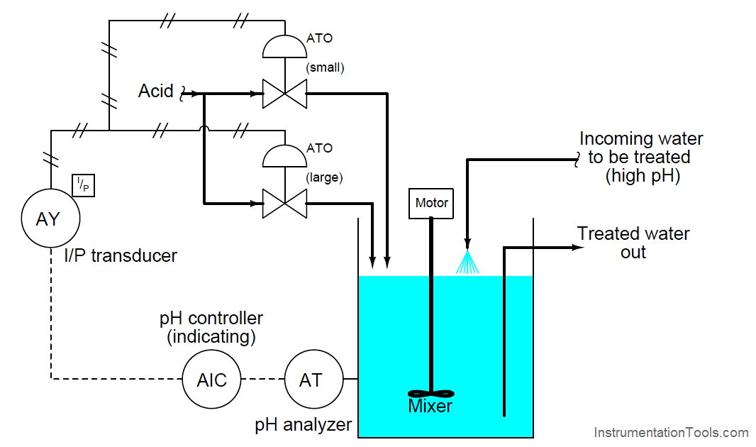
Applying this solution to a pH control process where the incoming liquid always has a high pH value, and must be neutralized with acid:

Progressive Valve Sequencing

Proper sequencing of the small and large acid control valves is shown in the table and the graph:

Progressive Valve Sequencing Graph

Valve Sequence Graph

With the two acid control valves sequenced progressively, the control system will have significantly more rangeability necessary to regulate pH under widely varying process conditions.

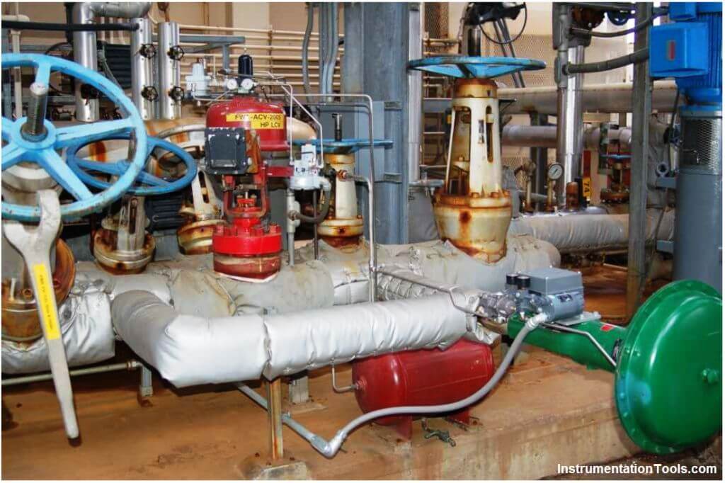
A photograph showing a pair of progressively sequenced control valves used to control boiler feedwater to the high-pressure (“HP”) drum on a large power boiler is shown here:

Control boiler feedwater

One small control valve (horizontal, with a green actuator) is the first to open from 4 to 12 mA. A larger control valve (vertical, with a red actuator) is the next to open from 12 mA to 20 mA.

Under normal (full-power) operating conditions, the green valve is wide-open while the larger red valve throttles feedwater to the steam drum. When the boiler is operating in standby (low-power) mode, the red valve is shut while the smaller green valve throttles feedwater to the steam drum.

The combination of these two control valves provides better steam drum level control over the boiler’s full range of operation than any single control valve could do alone.

Also Read : Basics of Actuators
Don't Miss Our Updates
Be the first to get exclusive content straight to your email.
We promise not to spam you. You can unsubscribe at any time.
Invalid email address
You've successfully subscribed !

Continue Reading

Basics of Control Valve Sizing
How to Protect Pumps from Cavitation? – Reasons, Solutions
Basic Parts of Control Valves
Solenoid Valves Types, Principle & Animation
What is Pump Cavitation? How to Avoid Cavitation?
What is a Hydraulic Actuator ?
Share This Article
Facebook Whatsapp Whatsapp LinkedIn Copy Link
Share
Leave a Comment

Leave a Reply Cancel reply

Your email address will not be published. Required fields are marked *

Stay Connected

128.3kFollowersLike
69.1kFollowersFollow
210kSubscribersSubscribe
38kFollowersFollow

Categories

Explore More

SIS Final Control Elements
PID Controller Action : Directing Acting & Reverse Acting
Types of Control Valves Noise
Control Valve Parts Questions and Answers
Pressure Relief Valve Principle
Control Valve Stroke Test Procedure
Choked Flow of Control Valves
Control Valve Positioners

Keep Learning

Speed of Power Actuators

Speed of Actuators

Motor Operated Valve Problems and Troubleshooting

Motor Operated Valve Problems and Troubleshooting

Difference-between-pneumatic-electric-hydraulic-actuators

Difference between Pneumatic, Electrical & Hydraulic Actuators

How to do Control Valve Sizing

How do you do control valve sizing in Layman’s terms?

Valve Seat leakage Test

Valve Seat Leakage Test

Lift check valves

What is Lift Check Valve ?

Questions and Answers on Valves

Valve Quiz

electric motor actuator principle

What is a Electric Motor Actuator ?

Learn More

Strain Gauge Pressure Transducer

Resistance Type Pressure Transducers Principle

Advantages of Pneumatic Systems in the Automotive Industry

Advantages of Pneumatic Systems in the Automotive Industry

Difference between Availability, Reliability & SIL

Difference between Availability, Reliability & SIL

Industrial Drives Multiple Choice Questions and Answers

Industrial Drives Multiple Choice Questions and Answers

Metering pumps

Metering Pumps

Shift Bit Register in PLC

Shift Bit Register in PLC

intouch Basics

How to Create Project in Wonderware Intouch?

Single Phase Preventer Relay

Working Principle of Single Phase Preventer Relay

Menu

  • About
  • Privacy Policy
  • Copyright

Quick Links

  • Learn PLC
  • Helping Hand
  • Part Time Job

YouTube Subscribe

Follow US
All rights reserved. Reproduction in whole or in part without written permission is prohibited.
Welcome Back!

Sign in to your account

Username or Email Address
Password

Lost your password?