What is HART ?
HART stands for ‘Highway Addressable Remote Transducer’ and is a standard originally developed as a communications protocol for control field devices operating on a 4-20 mA control signal.
The HART protocol uses 1200 baud Frequency Shift Keying (FSK) based on the Bell 202 standard to superimpose digital information on the conventional 4-20 mA analogue signal. Maintained by an independent organisation, the HART Communication Foundation, the HART protocol is an industry standard developed to define the communications protocol between intelligent field devices and a control system.
HART technology is a master/slave protocol, which means that a smart field (slave) device only speaks when spoken to by a master. The HART Protocol can be used in various modes such as point-to-point or multidrop for communicating information to/from smart field instruments and central control or monitoring systems.
HART Communication occurs between two HART-enabled devices, typically a smart field device and a control or monitoring system. Communication occurs using standard instrumentation grade wire and using standard wiring and termination practices.
The HART Protocol provides two simultaneous communication channels: the 4-20mA analog signal and a digital signal. The 4-20mA signal communicates the primary measured value (in the case of a field instrument) using the 4-20mA current loop – the fastest and most reliable industry standard. Additional device information is communicated using a digital signal that is superimposed on the analog signal.
The digital signal contains information from the device including device status, diagnostics, additional measured or calculated values, etc. Together, the two communication channels provide a low-cost and very robust complete field communication solution that is easy to use and configure.
HART is probably the most widely used digital communication protocol in the process industries, and:
- Is supported by all of the major suppliers of process field instruments.
- Preserves existing control strategies by allowing 4-20 mA signals to co-exist with digital communication on existing 2-wire loops.
- Is compatible with analogue devices.
- Provides important information for installation and maintenance, such as Tag-IDs, measured values, range and span data, product information and diagnostics.
- Can support cabling savings through use of multidrop networks.
- Reduces operating costs via improved management and utilisation of smart instrument networks.
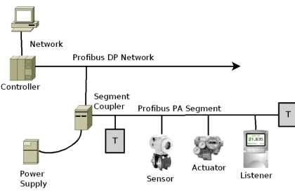
What is PROFIBUS ?
PROFIBUS is an open fieldbus standard for a wide range of applications in manufacturing and process automation independent of manufacturers. Manufacture independence and transparency are ensured by the international standards EN 50170, EN 50254 and IEC 61158.
It allows communication between devices of different manufacturers without any special interface adjustment. PROFIBUS can be used for both high-speed time critical applications and complex communication tasks. PROFIBUS offers functionally graduated communication protocols DP and FMS. Depending on the application, the transmission technologies RS-485, IEC 1158-2 or fibre optics can be used.
It defines the technical characteristics of a serial Fieldbus system with which distributed digital programmable controllers can be networked, from field level to cell level. PROFIBUS is a multi-master system and thus allows the joint operation of several automation, engineering or visualization systems with their distributed peripherals on one bus.
At sensor/actuator level, signals of the binary sensors and actuators are transmitted via a sensor/actuator bus. Data are transmitted purely cyclically.
At field level, the distributed peripherals, such as I/O modules, measuring transducers, drive units, valves and operator terminals communicate with the automation systems via an efficient, real-time communication system. As with data, alarms, parameters and diagnostic data can also be transmitted cyclically if necessary.
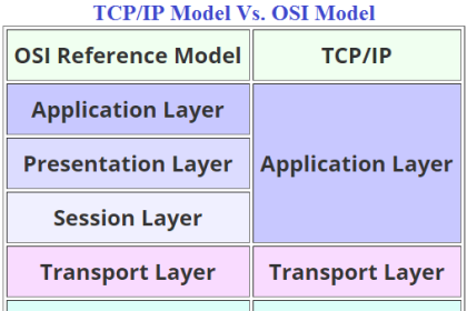
At cell level, programmable controllers such as PLC and IPC can communicate with each other. The information flow requires large data packets and a large number of powerful communication functions, such as smooth integration into company-wide communication systems, such as Intranet and Internet via TCP/IP and Ethernet.
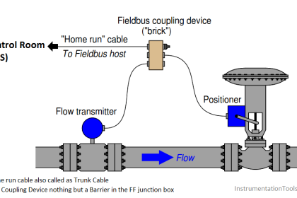
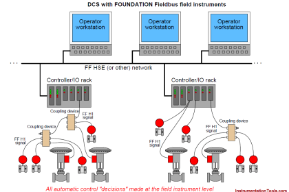
What is Foundation Fieldbus?
Foundation Fieldbus is an all-digital, serial, two-way communications system that serves as a Local Area Network (LAN) for factory/plant instrumentation and control devices. The Fieldbus environment is the base level group of the digital networks in the hierarchy of plant networks. Foundation™ Fieldbus is used in both process and manufacturing automation applications and has a built-in capability to distribute the control application across the network.
Unlike proprietary network protocols, Foundation Fieldbus is neither owned by any individual company, nor regulated by a single nation or standards body. The Foundation Fieldbus, a not-for-profit organization consisting of more than 100 of the world’s leading controls and instrumentation suppliers and end users, controls the technology.
While Foundation Fieldbus retains many of the desirable features of the 4-20 mA analogue system, such as a standardized physical interface to the wire, bus-powered devices on a single wire, and intrinsic safety options, it also offers many other benefits.
Device interoperability
Foundation Fieldbus offers interoperability; one Fieldbus device can be replaced by a similar device with added functionality from a different supplier on the same Fieldbus network while maintaining specified operations. This permits users to ‘mix and match’ field devices and host systems from various suppliers. Individual Fieldbus devices can also transmit and receive multivariable information, and communicate directly with each other over a common Fieldbus, allowing new devices to be added to the Fieldbus without disrupting services.