From VFD speed references (0–10 V = 0–100% speed) to HVAC damper feedback, lighting dimmers, actuator positions, and lab DAQ sensors, the 0–10 V analog signal is a staple wherever short cable runs and low-cost controllers are common. A PLC’s analog output might send 6.3 V to command a pump at 63% speed, while a room sensor returns 2.1 V to report temperature or CO₂ levels.
The problem: raw volts don’t tell an operator anything. Seeing 6.8 V on an input card means nothing until you scale it into engineering units like °C, bar, % open, RPM, lux, etc. This guide and the calculator convert any 0–10 V reading into a real value instantly, accurately, and repeatably.
Objective of the Tool
This tool provides a fast, error-free way to convert a measured 0–10 V analog signal into its engineering value, given the instrument’s configured minimum and maximum.
This tool helps you:
- Eliminate manual math during commissioning and troubleshooting
- Validate PLC/SCADA scaling blocks quickly
- Teach students the concept of linear scaling
- Diagnose out-of-range or noisy signals
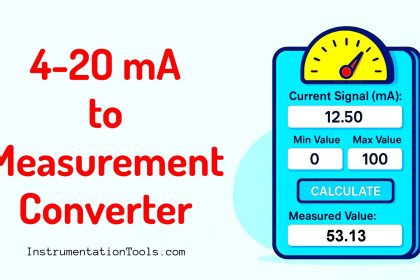
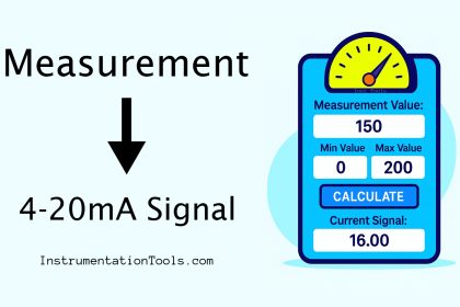
0–10 V to Measurement Converter
0-10V Signal to Measurement Value Converter Formula
Because the scaling is linear over 0–10 V, we use the following formula:
Measurement = Min + ((V – 0) / 10) × (Max – Min)
Formula
Where:
- V = Measured voltage (0–10 V range)
- Min = Engineering value at 0 V
- Max = Engineering value at 10 V
Explanation of the Formula
- (V – 0) – Since the low end is 0 V, subtracting 0 leaves the actual voltage. If your low end were 2 V (2–10 V), you’d subtract 2 instead.
- (V – 0) / 10 – Divide by the total span (10 V) to get a fraction (0.0 → 1.0) of the range.
- (Max – Min) – The engineering span. Example: 0–100 °C → span 100.
- Fraction × Span – Converts the fraction into engineering units.
- Min + … – Shifts the scaled value up to start at the correct minimum.
Assumptions: the sensor output is linear, wiring is sound, and the input card is calibrated. Noise, voltage drop, or grounding issues can still cause errors.
Key Terms to Know
| Term | Description |
|---|---|
| V (Volt) | Analog voltage representing the process value |
| Min | Engineering value at 0 V |
| Max | Engineering value at 10 V |
| Span | Max – Min, the full engineering range |
| Linear scaling | Direct proportionality between signal and measurement |
| ADC | Analog-to-Digital Converter inside PLC/DAQ that digitizes the voltage |
How to Use the Converter
- Enter Voltage (V): The value read by your PLC/DAQ/multimeter (e.g., 7.2 V).
- Enter Min: The process value at 0 V.
- Enter Max: The process value at 10 V.
- Click “Calculate.”
- Read the result: The tool shows the measurement (2 decimal places by default).
10 Detailed Beginner‑Friendly Examples
Example 1 – VFD Speed Command for a Cooling Pump
Question: A VFD accepts 0–10 V = 0–1500 RPM as its speed reference. The PLC AO is sending 3.8 V. What RPM is being commanded?
Solution:
Measurement = 0 + ((3.8 – 0) / 10) × (1500 – 0)
= (3.8 / 10) × 1500
= 0.38 × 1500
= 570 RPM
Example 2 – HVAC Damper Position Feedback
Question: A fresh‑air damper actuator feeds back 0–10 V for 0–90° blade angle. The system input reads 1.6 V. What angle should be displayed?
Solution:
Measurement = 0 + ((1.6 – 0) / 10) × (90 – 0)
= (1.6 / 10) × 90
= 0.16 × 90
= 14.4°
Example 3 – Chlorine Analyzer Output to SCADA
Question: A chlorine analyzer outputs 0–10 V for 0–5.0 ppm. SCADA logs 7.9 V. What residual chlorine is present?
Solution:
Measurement = 0 + ((7.9 – 0) / 10) × (5.0 – 0)
= 0.79 × 5.0
= 3.95 ppm
Example 4 – Displacement Sensor on a Press Machine
Question: A linear potentiometric transducer sends 0–10 V for 0–250 mm stroke. During setup, the PLC reads 0.85 V. How far has the ram moved?
Solution:
Measurement = 0 + ((0.85 – 0) / 10) × (250 – 0)
= 0.085 × 250
= 21.25 mm
Example 5 – Conductivity Probe (Offset Minimum)
Question: A conductivity transmitter is ranged 0–10 V = 50 µS/cm to 1050 µS/cm. The voltage is 6.0 V. What conductivity should be displayed?
Solution:
Measurement = 50 + ((6.0 – 0) / 10) × (1050 – 50)
= 50 + 0.6 × 1000
= 650 µS/cm
Example 6 – Solar Irradiance Sensor
Question: A pyranometer outputs 0–10 V for 0–1200 W/m². Logger reads 9.25 V. Calculate irradiance.
Solution:
Measurement = 0 + ((9.25 – 0) / 10) × 1200
= 0.925 × 1200
= 1110 W/m²
Example 7 – Torque Sensor on Test Bench
Question: A torque sensor delivers 0–10 V = 0–250 N·m. The DAQ channel reads 2.2 V during a test. Compute the torque.
Solution:
Measurement = 0 + ((2.2 – 0) / 10) × 250
= 0.22 × 250
= 55 N·m
Example 8 – Ultrasonic Level with Offset Range
Question: An ultrasonic level sensor is configured 0–10 V = 0.30 m to 4.30 m (distance). The analog input shows 7.0 V. What distance should be logged?
Solution:
Measurement = 0.30 + ((7.0 – 0) / 10) × (4.30 – 0.30)
= 0.30 + 0.7 × 4.00
= 0.30 + 2.80
= 3.10 m
Example 9 – Light Intensity (Lux) Sensor
Question: A lux sensor feeds 0–10 V for 0–2000 lux. Early morning voltage = 0.55 V. What lux should the controller calculate?
Solution:
Measurement = 0 + ((0.55 – 0) / 10) × 2000
= 0.055 × 2000
= 110 lux
Example 10 – Load Cell Amplifier Output
Question: A load cell conditioner outputs 0–10 V for 0–500 kg. The panel meter reads 6.45 V. Determine the weight.
Solution:
Measurement = 0 + ((6.45 – 0) / 10) × 500
= 0.645 × 500
= 322.50 kg
9. Benefits of Using This Converter
- Zero math mistakes – the formula is baked in
- Fast – great for on-site checks and commissioning
- Teaching aid – clarifies linear scaling for beginners
- Diagnostic helper – try over/under-range values to spot issues
Disadvantages / Limitations of 0–10 V Signals
| Limitation | Why It Matters |
|---|---|
| Voltage drop over distance | Long cables drop voltage; the PLC may read lower than the source |
| Noise susceptibility | Voltage signals pick up EMI/RFI more than current loops |
| Shared ground required | Ground loops can introduce offsets and noise |
| 0 V can mean zero OR fault | Broken wire looks like a valid 0 V reading |
| Low-end resolution | Tiny voltage changes near 0 V can be buried in noise/ADC error |
| Cannot power 2‑wire devices | Unlike 4–20 mA, 0–10 V can’t loop‑power transmitters |
11. Practical Use Cases
- HVAC/BMS sensors: temperature, humidity, CO₂, VOC
- Lighting dimming and actuator position feedback
- VFD analog speed references (0–10 V command)
- OEM machine sensors: displacement, torque, force, pressure
- Laboratory DAQ modules expecting voltage inputs
- Educational trainers and simulation benches
FAQ on 0–10 V Signals
1. What does a “0–10 V signal” actually mean?
A 0–10 V signal is a linear analog voltage used to represent a real-world variable.
- 0 V corresponds to the minimum engineering value (Min).
- 10 V corresponds to the maximum engineering value (Max).
Every voltage in between scales proportionally. If a temperature transmitter is set for 0–10 V = 0–100 °C, then 5 V means 50 °C, 7 V means 70 °C, and so on. This makes it easy to convert volts to meaningful numbers with one simple formula:
Measurement = Min + (V / 10) × (Max – Min).
2. Is the relationship between voltage and measurement always linear?
For standard 0–10 V transmitters, yes—linearity is assumed. The device is designed so each additional volt represents an equal step in the measured value.
- If the sensor itself is non‑linear (like many pH or thermistor sensors), the transmitter usually linearizes it internally before outputting 0–10 V.
- If not, you’ll need to perform your own linearization (lookup tables or math blocks) after converting the voltage.
3. Where is 0–10 V commonly used?
You’ll see 0–10 V everywhere in building automation and OEM machinery:
- HVAC/BMS: temperature, humidity, CO₂, damper position, VAV box control.
- Lighting: dimming control (0 V = off, 10 V = full brightness).
- Drives & Actuators: VFD speed references, valve/actuator position feedback.
- Lab/bench setups: DAQ modules and test rigs that read simple voltage signals.
It’s popular because it’s easy to implement, components are cheap, and runs are usually short.
4. Do I need a common ground with 0–10 V signals?
Yes. A voltage is measured relative to a ground (reference). The transmitting device and the receiving device (PLC/DAQ) must share a common reference for the reading to be accurate.
- Without a shared ground, you introduce offsets or floating readings.
- Use a single-point grounding strategy to avoid ground loops (ground at one end of the cable, not both).
5. Can 0 V indicate both a true zero and a broken wire?
Unfortunately, yes. If a cable snaps or a terminal comes loose, the input may read 0 V—the same as a legitimate “zero” measurement. To handle this:
- Add logic: if the value is stuck at exactly 0.00 V for too long, raise a diagnostic alarm.
- Some input cards provide open‑circuit detection—use them if available.
- Consider using a range like 2–10 V where 0 V clearly flags a fault.
6. Can a 0–10 V signal power a 2‑wire transmitter?
No. 0–10 V is purely a signal. You still need a separate power supply for most sensors/transmitters.
- With 4–20 mA loops, the current itself can power a 2‑wire device.
- With 0–10 V, you typically have a powered transmitter that outputs a voltage, or a passive device that needs an external source.
7. What input impedance should my PLC/DAQ have?
Aim for high input impedance (≥100 kΩ). A low impedance input will “load” the signal—drawing current and pulling the voltage down, so the reading becomes artificially low.
- Check your card specs. Most decent PLC/DAQ analog inputs already meet this.
- If you must connect multiple devices to one 0–10 V sensor, buffer the signal or use a splitter to avoid loading.
8. How do I scale 0–10 V to engineering units in a PLC or SCADA?
Use the linear formula:
Measurement = Min + (V / 10) × (Max – Min)
Implementation tips:
- Many PLCs have built‑in SCALE blocks—set raw min/max = 0 and 10, eng min/max = your range.
- In SCADA/HMI tags, do the same: raw 0–10, scaled to engineering limits.
- Always document Min/Max values used so future engineers know the assumptions.
9. What’s the difference between 0–10 V and 2–10 V signals?
2–10 V shifts the low end to 2 V so 0 V clearly indicates a wiring fault. It’s common in some HVAC controls.
- Formula changes to: Measurement = Min + ((V – 2) / 8) × (Max – Min).
- Any reading below ~2 V is treated as an error condition, not a valid measurement.
10. How far can I run a 0–10 V cable before accuracy suffers?
There’s no strict limit, but longer runs = more problems: voltage drop, noise pickup, and ground issues.
- For most building systems, keep runs under a few tens of meters.
- For longer distances or noisy areas, it’s better to convert to 4–20 mA (less susceptible to voltage drop/noise) or use a signal conditioner locally.
11. How do I check a 0–10 V signal with a multimeter?
- Set the multimeter to DC volts.
- Measure across the signal terminal and ground.
- Compare the reading to the expected engineering value using the scaling formula.
If what you measure doesn’t match what the PLC says, you may have wiring, loading, or scaling issues.
12. My input module reads ±10 V. Does that change the math?
No. You still scale 0–10 V the same way. The module can also see negative voltages, but your transmitter shouldn’t output them.
- In your logic, clamp negative readings to zero or treat them as faults.
- Only change the formula if your sensor truly spans a negative range.
13. How do I reverse-calculate the voltage from a known measurement?
Use the inverse formula:
V = ((Measurement – Min) / (Max – Min)) × 10
This is handy if you want to generate a test voltage from a calibrator or AO card to simulate a certain engineering value on a PLC input.
14. How do I protect a 0–10 V signal from noise and interference?
- Cabling: Use shielded twisted pair, keep analog lines separate from power/VFD cables.
- Grounding: Ground the shield at one end only to avoid loops.
- Software: Apply a low-pass or moving-average filter in the PLC/HMI to smooth spikes.
- Hardware: Use RC filters, ferrite beads, or isolated signal conditioners if noise is severe.
15. Why would I choose 0–10 V over 4–20 mA (or vice versa)?
Choose 0–10 V when:
- Distances are short and environment is relatively clean (little EMI).
- Hardware is cheaper/simpler (BMS, small OEM panels).
- Multiple signals are handled on a common ground easily.
Choose 4–20 mA when:
- Runs are long or in harsh, noisy industrial areas.
- You want loop-powered 2‑wire transmitters.
- You need clear fault detection (0 mA = open circuit).
Both standards are valid—pick the one that fits the application’s distance, noise, and power needs.
Conclusion
The 0–10 V Signal to Measurement Converter takes the guesswork out of analog scaling. Whether you’re validating PLC logic, tuning a BMS loop, or teaching the basics of instrumentation, this tool (and the math behind it) keeps your numbers consistent.
