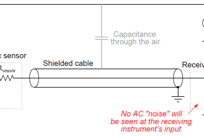
Special-purpose electronic test instruments called loop calibrators exist for the express purpose of 4-20 mA current loop circuit troubleshooting.
These versatile instruments are generally capable of not only measuring current, but also sourcing current to unpowered devices in a loop, and also simulating loop-powered 4-20 mA transmitters.
A loop calibrator unit is a hand-held unit with a rotary knob for current adjustment (analog type) and toggle switches for mode setting. The following illustration shows how this calibrator would be used to measure current in a functioning input signal loop:
Note : In the following illustrated examples, the transmitter is assumed to be a pressure transmitter with a calibrated range of 0 to 750 inches of water column, 4-20 mA.
The controller’s PV (process variable) display is appropriately ranged to display 0 to 750 as well.
Loop Calibrator
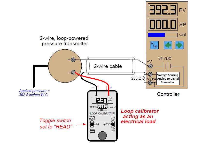
Here, the loop wiring is broken at the negative terminal of the loop-powered transmitter, and the calibrator connected in series to measure current. If this loop had a test diode installed, the calibrator could be connected in parallel with the diode to achieve the same function.
Note the polarity of the calibrator’s test leads in relation to the circuit being tested:
the calibrator is acting as a passive device (i.e. as a load rather than as a source), with the more positive loop terminal connected to the calibrator’s red test lead and the more negative terminal connected to the black test lead.
The same loop calibrator may be used to source (or drive) a 4-20 mA signal into an indicating instrument to test the function of that instrument independently.
Here, we see the Altek calibrator used as a current source to send a 16.00 mA signal to the PV (process variable) input of the controller, in order to check that the controller properly senses and displays the analog current signal:
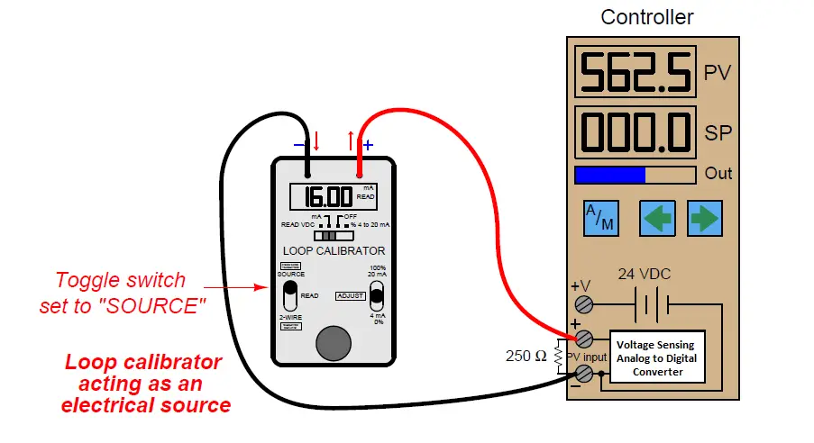
No transmitter need be included in this illustration, because the calibrator takes its place. Note how the calibrator functions here as an active source of current rather than a passive load as it was in the last example.
Not only does it supply the information (i.e. regulate the current), but it also provides the energy in the circuit. The DC power source inside the controller is not used for loop power, because the calibrator in “source” mode provides the necessary power to drive current through the 250 ohm resistor.
A very common use of a loop calibrator in “source” mode is to test a control valve for proper calibration, quick response, and to measure friction.
Here, the loop calibrator takes place of the loop controller output, serving as the sole source of current to the I/P transducer:
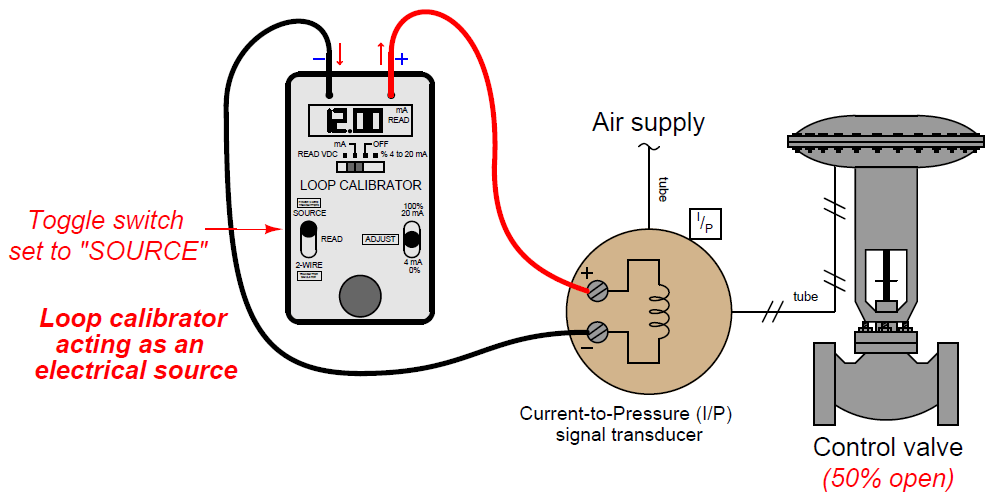
This circuit configuration is extremely useful to any instrument technician testing the response of a control valve, because it allows the signal to be finely adjusted while in the direct presence of the valve to monitor its motion.
If a control valve is suspected of having excessive friction in its moving parts, for instance, a technician may test the valve by incrementing and decrementing the loop calibrator’s source current in progressively smaller steps.
Large step-changes in current should cause the valve to overcome friction and move, but small step-changes will fail to move the valve mechanism when frictional forces exceed the incremental forces produced by the changing pressure.
A photograph showing this very use of a loop calibrator in a valve rebuild shop appears here:
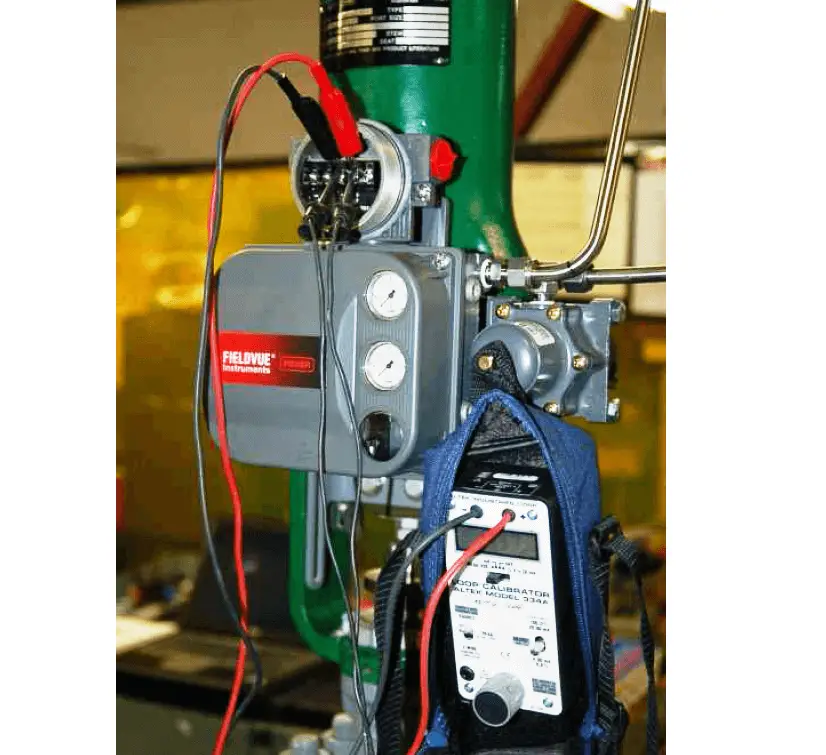
In this particular example, the loop calibrator connects to a device on the control valve called a positioner, which is a more sophisticated device than an I/P transducer.
In addition to converting a 4-20 mA signal into an air pressure, the positioner also actively monitors the valve stem’s position to ensure it goes to the correct position for any given 4-20 mA command signal.
Here, the technician is using the loop calibrator to verify the control valve faithfully obeys the command signal through the entire 4 to 20 milliamp signal range.
An alternative method of sending a known current signal into an indicating instrument providing loop power is to set the loop calibrator such that it mimics (or simulates) the behavior of a loop-powered (2-wire) transmitter.
In this mode, the calibrator regulates loop current at a userdetermined value, but provides no motivating voltage to drive this current. Instead, it passively relies on the loop’s regular voltage source to provide the necessary power:
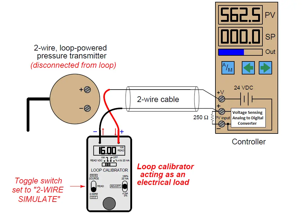
Note the polarity of the calibrator’s test leads: current entering the red lead and exiting the black lead, behaving as an electrical load just the same as a loop-powered transmitter.
Like a 2-wire transmitter, the calibrator in simulate mode regulates the circuit current while depending on an external voltage source for energy.
A loop calibrator’s simulate transmitter mode is especially useful for testing the transmitter cable and controller input to ensure any 4-20 mA signal sent by a transmitter will be correctly received and displayed by the controller.
This sort of test is commonly performed on newly-installed control systems as part of the commissioning procedure, prior to start-up of the controlled process, in order to verify the controller’s process variable input, 24 VDC power supply, and transmitter wiring are all properly functioning.
Typically an instrument technician would simulate several different current values (e.g. 4 mA, 8 mA, 12 mA, 16 mA, 20 mA) with the calibrator in “simulate” mode while someone else monitors the controller’s PV display and alarms to check for proper function.
A legacy loop calibrator still familiar to many instrument technicians at the time of this writing is the classic Transmation model 1040 (Left Side):
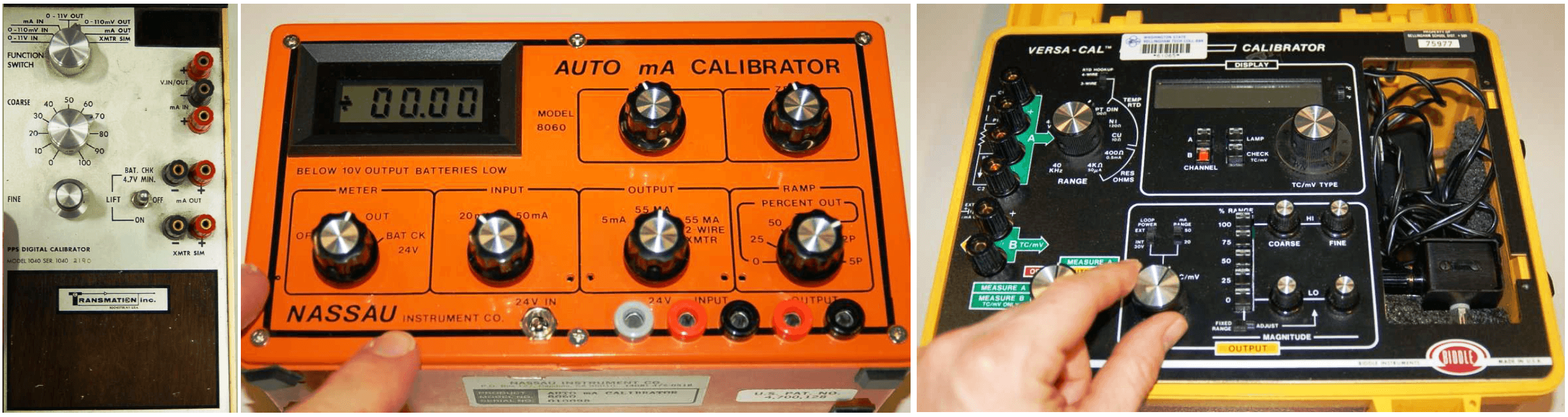
Other examples of vintage loop calibrator technology include the Nassau model 8060 (center) and the Biddle Versa-Cal (right):
A modern loop calibrator manufactured by Fluke is the model 705:
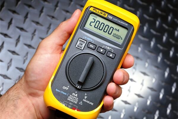
With this calibrator, the measure, source, and simulate modes are accessed by repeatedly pushing a button, with the current mode displayed on the screen:
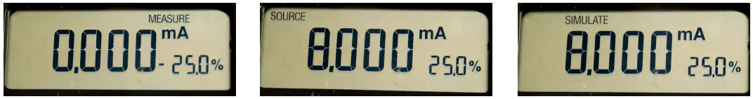
Note the dual-numeric display, showing both loop current and percentage (assuming a 4-20 mA range).
Credits : by Tony R. Kuphaldt – Creative Commons Attribution 4.0 License