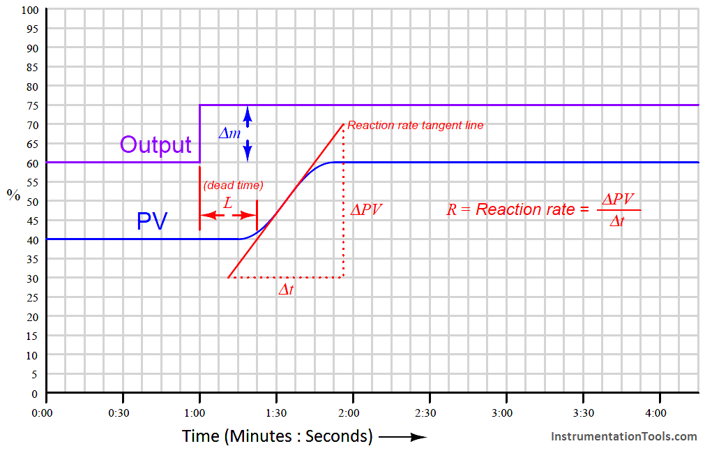
In contrast to the first tuning technique presented by Ziegler and Nichols in their landmark 1942 paper where the process was made to oscillate using proportional-only automatic control and the parameters of that oscillation served to define PID tuning parameters, their second tuning technique did not even rely on the presence of a controller. Instead, this second technique consisted of making a manual “step-change” of the control element (valve) and analyzing the resulting effect on the process variable.
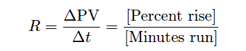
After making the step-change in output signal with the controller in manual mode, the process variable trend is closely analyzed for two salient features: the dead time and the reaction rate. Dead time (L) (Note 1) is the amount of time delay between the output step-change and the first indication of process variable change. Reaction rate is the maximum rate at which the process variable changes following the output step-change (the maximum time-derivative of the process variable):
Note 1 : Unfortunately, Ziegler and Nichols chose to refer to dead time by the word lag. In modern technical parlance, “lag” refers to a first-order inverse-exponential function, which is fundamentally different from dead time.
Dead time and reaction rate are responses common to self-regulating and integrating processes alike. Whether or not the process variable ends up stabilizing at some new value, its rate of rise will reach some maximum value following the output step-change, and this will be the reaction rate of the process (Note 2).
Note 2 : Right away, we see a weakness in the Ziegler-Nichols open-loop method: it makes absolutely no distinction between self-regulating and integrating process types. We know this is problematic from the analysis of each process type.
The unit of measurement for reaction rate is percent per minute:
While dead time in a process tends to be constant regardless of the output step-change magnitude, reaction rate tends to vary directly with the magnitude of the output step-change. For example, an output step-change of 10% will generally cause the PV to rise at a rate twice as steep compared to the effects of a 5% output step-change. In order to ensure our predictive calculations capture only what is inherent to the process and not our own arbitrary open-loop tuning actions, we must include the output step-change magnitude (Δm) in those calculations as well (Note 3 ).
Note 3 : Ziegler and Nichols’ approach was to define a normalized reaction rate called the unit reaction rate, equal in value to R/Δm. I opt to explicitly include Δm in all the tuning parameter equations in order to avoid the possibility of confusing reaction rate with unit reaction rate.
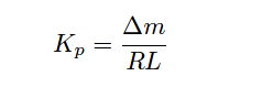
If the controller in question is proportional-only (i.e. capable of providing no integral or derivative control actions), Ziegler and Nichols’ recommendation is to set the controller gain as follows:
 Where,
Kp = Controller gain value that you should enter into the controller for good performance
Δm = Output step-change magnitude made while testing in open-loop (manual) mode (percent)
R = Process reaction rate = ΔPV/Δt (percent per minute)
L = Process dead time (minutes)
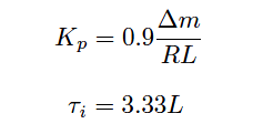
If the controller in question has integral (reset) action in addition to proportional, Ziegler and Nichols’ recommendation is to set the controller gain to 90% of the proportional-only value, and to set the integral time constant to a value just over three times the measured dead time value:
Where,
Kp = Controller gain value that you should enter into the controller for good performance
Δm = Output step-change magnitude made while testing in open-loop (manual) mode (percent)
R = Process reaction rate = ΔPV/Δt (percent per minute)
L = Process dead time (minutes)
τi = Controller integral setting that you should enter into the controller for good performance (minutes per repeat)
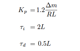
If the controller has full PID capability, Ziegler and Nichols’ recommendation is to set the controller gain to 120% of the proportional-only value, to set the integral time constant to twice the measured dead time value, and to set the derivative time constant to one-half the measured dead time value:
Where,
Kp = Controller gain value that you should enter into the controller for good performance
Δm = Output step-change magnitude made while testing in open-loop (manual) mode (percent)
R = Process reaction rate = ΔPV/Δt (percent per minute)
L = Process dead time (minutes)
τi = Controller integral setting that you should enter into the controller for good performance (minutes per repeat)
τd = Controller derivative setting that you should enter into the controller for good performance (minutes)
As you can see, the Ziegler-Nichols open-loop tuning method relies heavily on dead time (L) as a descriptive parameter for the process. This may be problematic in processes having insubstantial dead time, as the small L values obtained during the open-loop test will predict large controller gain (Kp) and aggressive integral (τi) time constant values, often too large to be practical. The open-loop method, however, is less disruptive to an operating process than the closed-loop method (which necessitated over-tuning the controller to the brink of total instability).
Another limitation, common to both the closed-loop and open-loop tuning methods, is that other factors in the process such as noise and hysteresis are completely overlooked. Noise is troublesome for large controller gain values (because the controller’s proportional action reproduces that noise on the output) and is especially troublesome for derivative action which amplifies any noise it sees. Hysteresis causes integral action to continually “hunt” up and down, leading to cycling of the process variable. The lesson here is that no algorithmic PID tuning method can replace informed judgment on the part of the person tuning the loop. The methods proposed by Ziegler and Nichols (and others!) are merely starting points, and should never be taken as a definitive answer for controller tuning.
Also Read : Ziegler-Nichols Closed-Loop Method