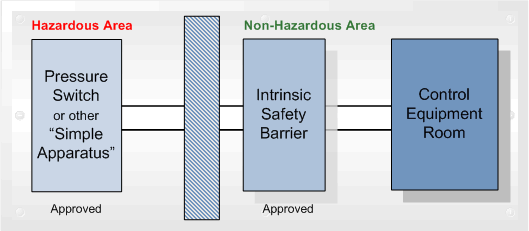
Intrinsic safety (IS) is a low-energy signalling technique that prevents explosions from occurring by ensuring that the energy transferred to a hazardous area is well below the energy required to initiate an explosion.
Intrinsic safety
The energy levels made available for signalling are small but useable and more than adequate for the majority of instrumentation systems.
The two mechanisms being considered that could initiate an explosion are:
- A spark
- A hot surface
The advantages of intrinsic safety
The major advantage of intrinsic safety is that it provides a solution to all the problems of hazardous areas (for equipment requiring limited power) and is the only technique which meets this criterion.
The significant factors are as follows:
a) The IS technique is accepted throughout the There is an increasing acceptance of international certificates issued under the IEC Ex scheme but this has some way to go. Intrinsic safety is an acceptable technique in all local legislation such as the ATEX Directives and OSHA. The relevant standards and code of practice give detailed guidance on the design and use of intrinsically safe equipment to a level which is not achieved by any of the other methods of protection.
b) The same IS equipment usually satisfies the requirements for both dust and gas
c) Appropriate intrinsically safe apparatus can be used in all In particular, it is the only solution that has a satisfactory history of safety for Zone 0 instrumentation. The use of levels of protection (‘ia’, ‘ib’ and ‘ic’) ensures that equipment suitable for each level of risk is available (normally ‘ia’ is used in Zone 0, ‘ib’ in Zone 1 and ‘ic’ in Zone 2
d) Intrinsically safe apparatus and systems are usually allocated a group IIC gas classification which ensures that the equipment is compatible with all gas/air Occasionally, IIB systems are used, as this permits a higher power level to be used. (However, IIB systems are not compatible with acetylene, hydrogen and carbon disulfide.)
e) A temperature classification of T4 (135°C) is normally achieved, which satisfies the requirement for all industrial gases except carbon disulfide (CS ) which, fortunately, is rarely
f) Frequently, apparatus, and the system in which it is used, can be made ‘ia IIC T4’ at an acceptable This removes concerns about area classification, gas grouping and temperature classification in almost all circumstances and becomes the universal safe solution.
g) The ‘simple apparatus’ concept allows many simple pieces of apparatus, such as switches, thermocouples, RTD’s and junction boxes to be used in intrinsically safe systems without the need for certifica This gives a significant amount of flexibility in the choice of these ancillaries.
h) The intrinsic safety technique is the only technique that permits live maintenance within the hazardous area without the need to obtain ‘gas clearance’ certifica This is particularly important for instrumentation, since fault-finding on de- energised equipment is difficult.
i) The installation and maintenance requirements for intrinsically safe apparatus are well documented, and consistent regardless of level of This reduces the amount of training required and decreases the possibility of dangerous mistakes.
j) Intrinsic safety permits the use of conventional instrumentation cables, thus reducing Cable capacitance and inductance is often perceived as a problem but, in fact, it is only a problem on cables longer than 400 metres, in systems installed in Zones 0 and 1, where IIC gases (hydrogen) are the source of risk. This is comparatively rare and, in most circumstances, cable parameters are not a problem.
Available power
Intrinsic safety is fundamentally a low energy technique and consequently the voltage, current and power available is restricted.
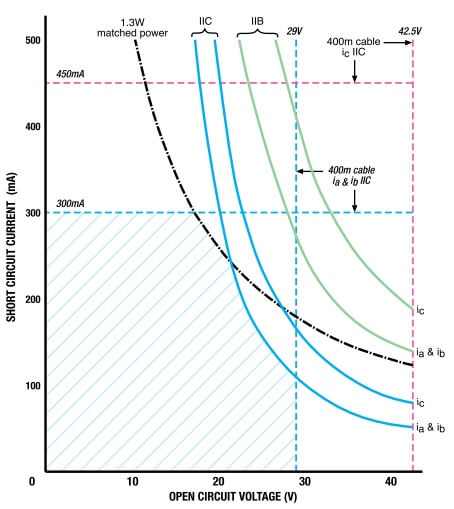
Figure 1.0 is a simplified illustration of the available power in intrinsically safe circuits and attempts to demonstrate the type of electrical installation in which the intrinsically safe technique is applicable.
The blue and green curves are the accepted design curves used to avoid spark ignition by resistive limited circuits in Group IIC and IIB gases. The ‘ic’ curves are less sensitive because they do not require the application of a safety factor in the same way as for
‘ia’ and ‘ib’ equipment. In general the maximum voltage available is set by cable capacitance (400 metres corresponds to 80nF which has a permissible voltage of 29V in ‘IIC ia’ circuits) and the maximum current by cable inductance (400 metres corresponds to 400µH which has a permissible current of 300 mA in IIC ia circuits). A frequently used limitation on power is the 1.3W, which easily permits a T4 (135°C) temperature classification. These limits are all shown in Figure 1.0
A simple approach is to say that if the apparatus can be operated from a source of power whose output parameters are within the (blue) hatched area then it can readily be made intrinsically safe to ‘ IIC ia T4’ standards. If the parameters exceed these limits to a limited degree then it can probably be made intrinsically safe to IIB or ‘ic’ requirements.
The first choice, however, is always to choose ‘IIC ia T4’ equipment, if it provides adequate power and is an economic choice, as this equipment can be used in all circumstances (except if carbon disulfide (CS ) is the hazardous gas, in which case there are other problems).
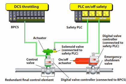
Also Read: Difference between DCS & PLC Systems
In practice almost all low voltage instrumentation can be made
‘IIB ic T4’ as the limits are set by the least sensitive of the ignition curves in Figure 1.0 (typically 24V 500 mA). The ‘IIB ic’ specification does restrict application to Zone 2 and where the hazardous gas is not hydrogen, acetylene or carbon disulfide but is still applicable to a large range of installations.
Conclusion
Intrinsic safety is the natural choice for all low voltage instrumentation problems. Adequate solutions exist which are compatible with all gases and area classifications. The technique prevents explosions rather than retains them which must be preferable, and the ‘live maintenance’ facility enables conventional instrument practice to be used.
Why use intrinsic safety?
The principal reason for using intrinsic safety is because it is essentially a low power technique. Consequently, the risk of ignition is minimized, and adequate safety can be achieved with a level of confidence that is not always achieved by other techniques.
It is difficult to assess the temperature rise, which can occur if equipment is immersed in a dust because of the many (frequently unpredictable) factors, which determine the temperature rise within the dust layer. The safest technique is therefore to restrict the available power to the lowest practical level.
A major factor in favor of intrinsic safety is that the power level under fault conditions is controlled by the system design and does not rely on the less well-specified limitation of fault power.
Intrinsic safety also has the advantage that the possibility of ignition from immersed or damaged wiring is minimised. It is desirable to be able to do ‘live maintenance’ on an instrument system, and the use of the intrinsically safe technique permits this without the necessity of special ‘dust free’ certificates.
There is a need to clear layers of dust carefully and to avoid contamination of the interior of apparatus during maintenance but this is apparent to any trained technician. (There is no significant possibility of a person, in a dust cloud that can be ignited, surviving without breathing apparatus).
To summarize, intrinsic safety is the preferred technique for instrumentation where dust is the hazard because:
- the inherent safety of intrinsic safety gives the greatest assurance of safety and removes concern over overheating of equipment and cables
- the installation rules are clearly specified and the system design ensures that all safety aspects are covered
- live maintenance is permitted
- equipment is available to solve the majority of problems
