Inst ToolsInst ToolsInst Tools
  • Courses
  • Automation
    • PLC
    • Control System
    • Safety System
    • Communication
    • Fire & Gas System
  • Instrumentation
    • Design
    • Pressure
    • Temperature
    • Flow
    • Level
    • Vibration
    • Analyzer
    • Control Valve
    • Switch
    • Calibration
    • Erection & Commissioning
  • Interview
    • Instrumentation
    • Electrical
    • Electronics
    • Practical
  • Q&A
    • Instrumentation
    • Control System
    • Electrical
    • Electronics
    • Analog Electronics
    • Digital Electronics
    • Power Electronics
    • Microprocessor
  • Request
Search
  • Books
  • Software
  • Projects
  • Process
  • Tools
  • Basics
  • Formula
  • Power Plant
  • Root Cause Analysis
  • Electrical Basics
  • Animation
  • Standards
  • 4-20 mA Course
  • Siemens PLC Course
Reading: Which Instrument is at Fault in this System?
Share
Font ResizerAa
Inst ToolsInst Tools
Font ResizerAa
  • Courses
  • Design
  • PLC
  • Interview
  • Control System
Search
  • Courses
  • Automation
    • PLC
    • Control System
    • Safety System
    • Communication
    • Fire & Gas System
  • Instrumentation
    • Design
    • Pressure
    • Temperature
    • Flow
    • Level
    • Vibration
    • Analyzer
    • Control Valve
    • Switch
    • Calibration
    • Erection & Commissioning
  • Interview
    • Instrumentation
    • Electrical
    • Electronics
    • Practical
  • Q&A
    • Instrumentation
    • Control System
    • Electrical
    • Electronics
    • Analog Electronics
    • Digital Electronics
    • Power Electronics
    • Microprocessor
  • Request
Follow US
All rights reserved. Reproduction in whole or in part without written permission is prohibited.
Inst Tools > Blog > Level Measurement > Which Instrument is at Fault in this System?

Which Instrument is at Fault in this System?

A level indicator is registering a liquid level that is falsely low. Which instrument is at fault in this system? How do you know?

Last updated: March 4, 2021 8:46 pm
Editorial Staff
Level Measurement Practical Questions
10 Comments
Share
1 Min Read
SHARE

A level indicator is registering a liquid level that is falsely low.

The operator has hand-gauged the storage vessel with a tape measure and determined the actual level to be 9 feet, but the level indicator (LI) registers 7.5 feet.

Which instrument is at fault in this system

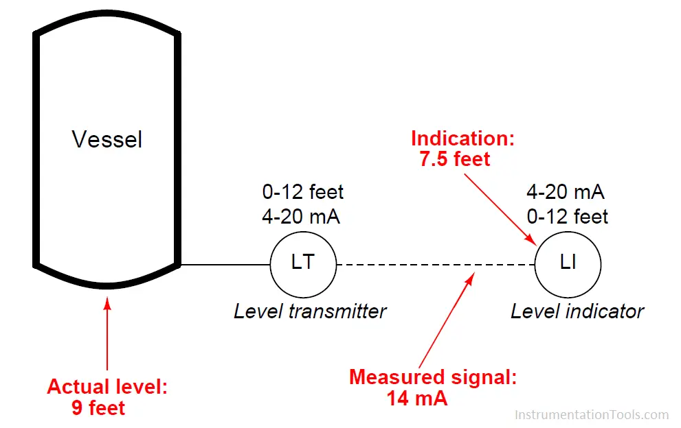
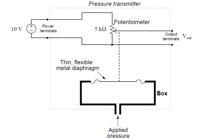
The calibrated range of the 4-20 mA transmitter is 0 feet to 12 feet.

You measure the current signal with your multimeter and find that it is 14 mA.

Which instrument is at fault in this system? How do you know?

Answer:

The transmitter is at fault, not the indicator.

Share your answers with us through below comments section.

Scroll down to see the answers shared by the users.

Read Next:

  • Transmitter Calibrate
  • Level Instruments
  • Radar Signal Strength
  • Dip Tube Level System
  • High Level Alarm

Credits: Tony R. Kuphaldt

Don't Miss Our Updates
Be the first to get exclusive content straight to your email.
We promise not to spam you. You can unsubscribe at any time.
Invalid email address
You've successfully subscribed !

Continue Reading

Level Sensors MCQ – Industrial Instrumentation
Troubleshooting PLC Permissive Inputs
Practical Process Control System Questions & Answers – 1
Identify the Purpose of Flow Ratio Controller
How Do You Connect the Differential Pressure Gauge at the Filter?
Level Measurement with Wet leg and Installed Below Tapping Point
Share This Article
Facebook Whatsapp Whatsapp LinkedIn Copy Link
Share
10 Comments
  • Claudio Ingravallo says:
    January 9, 2021 at 5:23 pm

    An indicator is usually connected in serial with the transmitter in the same circuit loop.

    It`s not the indicator the measuring device and the fault is likely to be in the transmitter and not otherwise.

    However, measuring the instrument`s output wherever in the loop is always the way to determine the right actual instrument`s output to the control system and frequently this is enough to solve the problem that we are dealing with but sometimes, STILL, it is not the guaranty that it will be processed in the right way by the control system (PLC or DCS) and displayed at DCS screen`s operator.

    Reply
  • Tikno says:
    January 9, 2021 at 8:49 pm

    The transmitter is calibrated in wrong range, if it is calibrated in 0-12 Feet the output should be 16 mA instead 14 mA.
    If the output is 14 mA with actual level is 9 feet then the LT calibration is 0-14..4 Feet.

    In other side the LI calibrated in correct range 0-12 Feet.

    Reply
  • OHamza says:
    January 10, 2021 at 10:22 pm

    Level Transmitter Should Be faulty … this could be on A sensor Primary element.
    Why?
    Each 3ft = 4mA
    9 ft => 4+12 mA = 16 mA => LT is generating a wrong signal
    14 mA => 7.5 ft => Li is rading Right

    Reply
  • Tiago Marques says:
    January 12, 2021 at 6:36 pm

    The LI is correctly outputing the level according to the amount of current received from the LT. A 14 ma current received from LT is correctly converted to 7.5 ft (heigh = 12ft*(14ma-4ma)/16)

    On the other hand, at an actual level of 9ft, the LT was expected to output a 16ma current ( (16*9/12) + 4). 75%

    Reply
  • Yap kok chuan says:
    February 5, 2021 at 6:25 pm

    Yes. There is a formula on this signal calculation.
    4mA.= 0.0 ft
    12mA = 6.0 ft
    20 mA = 12 ft

    So actual physical reading of 14 mA by a calibrated multimeter. It gives a 7.5 ft

    14mA – 4, divide by 16 then x height of 12 ft equals to 7.5 ft.

    Then the transmitter needs a calibration from Zero potential settings to 0.00 and the SPAN to 12 ft. When the signals goes back to the analog input card. 0.0 value of 333 bits and 12. 0 values of 4926 bits or FEE.

    Reply
  • Jmal Mnsor says:
    March 4, 2021 at 8:29 pm

    We have to do calibration for the transmitter 4_20 ..if the percentage error out of range (more than 0.25%) should be fix the transmitter (as left) by hard communicator .

    Reply
  • Al Hastie says:
    March 4, 2021 at 8:30 pm

    First of all, before you start to troubleshoot, you need to get permission from the operator to take the instrument out of service.

    You do not know if this level transmitter is connected to a shut down or is just an alarm.

    The second thing is to confirm what type of material it is measuring, is it water or is it acid, it could be anything you don’t know. Once these items are addressed, isolate, drain, and lock out the instrument.

    Once this is completed, pump up the transmitter with calibration equipment while measuring the milliamp output.

    If the instrument is out of calibration recalibrate and exercise the instrument for repeatability. If the instrument does not repeat and falls out of calibration replace the instrument.

    I agree the level transmitter is reading incorrectly, but what caused it? Getting the plant back online is important but finding out the reason for the failure is just as important

    Reply
  • Satish Sh says:
    March 4, 2021 at 8:31 pm

    Level transmitter measure level . 0 =4ma and 20 ma for 12ft Fault reading .need calibration if calibration fails need to replace transmitter do calibration empty levels and span for 12ft

    Reply
    • fadi says:
      November 25, 2021 at 12:57 pm

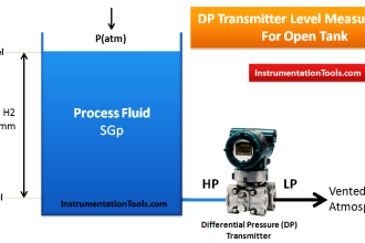
      the tank is close so the LT should be wet leg
      we need recalibrate LT case its range is 0 to 12 ftand the tank is just 9ft

      Reply
  • Amn Azmn says:
    March 4, 2021 at 8:31 pm

    LT should send 16mA signal.
    9′ x 16/12 = 16mA.
    But it sending only 14mA.
    So.. LT is the problem.

    Reply

Leave a Reply Cancel reply

Your email address will not be published. Required fields are marked *

Stay Connected

128.3kFollowersLike
69.1kFollowersFollow
210kSubscribersSubscribe
38kFollowersFollow

Categories

Explore More

Questions on Allen-Bradley MicroLogix 1000 PLC
Thermocouple Terminal block Questions
PT Loop Diagram Faults
Determine the Instrument Calibration Error
Smart DP Transmitter Flow Meter Calculations
Calculate the Transmitter Values
Float-type Level Switch to Control a pump
Tank Level Detection Switches

Keep Learning

Solenoid-controlled Valve Problem

Solenoid-controlled Valve Problem

Two Differential Pressure Transmitters

Pressure Level Transmitter Problems

process conditions, Find out the Circuit Components Status

As per Process Conditions, Find out the Circuit Components Status ?

displacer level transmitter cylindrical weighs

Displacer Level Transmitter 5-point Calibration

Programmable Logic Controller (PLC) Questions and Answers

Programmable Logic Controller (PLC) Questions and Answers – 7

Siemens S7-200 PLC Ladder Logic

Programmable Logic Controller (PLC) Questions and Answers – 10

Allen-Bradley MicroLogix controller

Programmable Logic Controller (PLC) Questions and Answers – 15

level-transmitter-calibration-procedure

Level Transmitter Calibration Procedure

Learn More

SCADA RTU TELEMETRY

SCADA & Telemetry Systems

Contact-Type-GWR-Level-Transmitter-Working-Animation

Probe Type GWR Level Transmitter Working Animation

Miniature Circuit Breakers Questions and Answers

Miniature Circuit Breakers Questions and Answers

Flame Detectors Working Principle

Flame Detectors Working Principle

Difference Between Wattmeter and Energy Meter

Difference Between Wattmeter and Energy Meter

Instrumentation Cyber Security

Instrumentation Cyber Security Glossary

What is PLC

What is a PLC? – Programmable Logic Controller

Power Electronics Objective Questions

Single Phase Voltage Source Inverter (VSI) Objective Questions

Menu

  • About
  • Privacy Policy
  • Copyright

Quick Links

  • Learn PLC
  • Helping Hand
  • Part Time Job

YouTube Subscribe

Follow US
All rights reserved. Reproduction in whole or in part without written permission is prohibited.
Welcome Back!

Sign in to your account

Username or Email Address
Password

Lost your password?