Wellhead control panel (WHCP) is used to provide hydraulic supply to the wellhead valves, choke valves, HIPPS, and fusible plug loops.
Wellhead valves include Christmas tree valves SSSVs, SSVs, UMVs, WVs.
These are normally hydraulic operated valves and WHCP will provide hydraulic oil for actuation of these valves and when all these valves are opened then fluid from the well comes out so fluid (Oil/water/gas) is transported and processed further. WHCP is applicable to oil & gas producing wells.
SSSV = Subsurface Safety Valve / DHV = Downhole Valve
SSV = Surface Safety Valves
UMV = Upper Master Valve
WV = Wing Valve
Wellhead Control Panel
Major components of WHCP is listed below but not limited to:
WHCP
WHCP is a cabinet that is a free-standing type and it has a hydraulic reservoir, pumps, electrical starter, accumulator, solenoids, relief valves, regulators, junction boxes, etc.
The material of WHCP should be SS316/L and should have IP 65 protection class, and sunshade/canopy for outdoor installation. It should have all instrumentation, electrical, and hydraulic circuit components as required for operation and a few of them are described below.
The WHCP panel is installed in the field near the well pad and it does not contain any controller part. PLC panels can be installed in a safe field area or in a controlled environment. Normally, Remote I/O panels are installed in the field for oil well-related operation interfaces.
Transportation and installation at site related things should be taken care of during the design phase itself.
All logical sequences of opening or closing of valves, shutdown commands, close and open commands will be provided by the PLC directly to the respective components within the WHCP such as solenoid valves, lamps, pushbuttons.
Status signals like Pressure/level will be connected to PLC via transmitters installed on the WHCP panel.
Hydraulic Pump
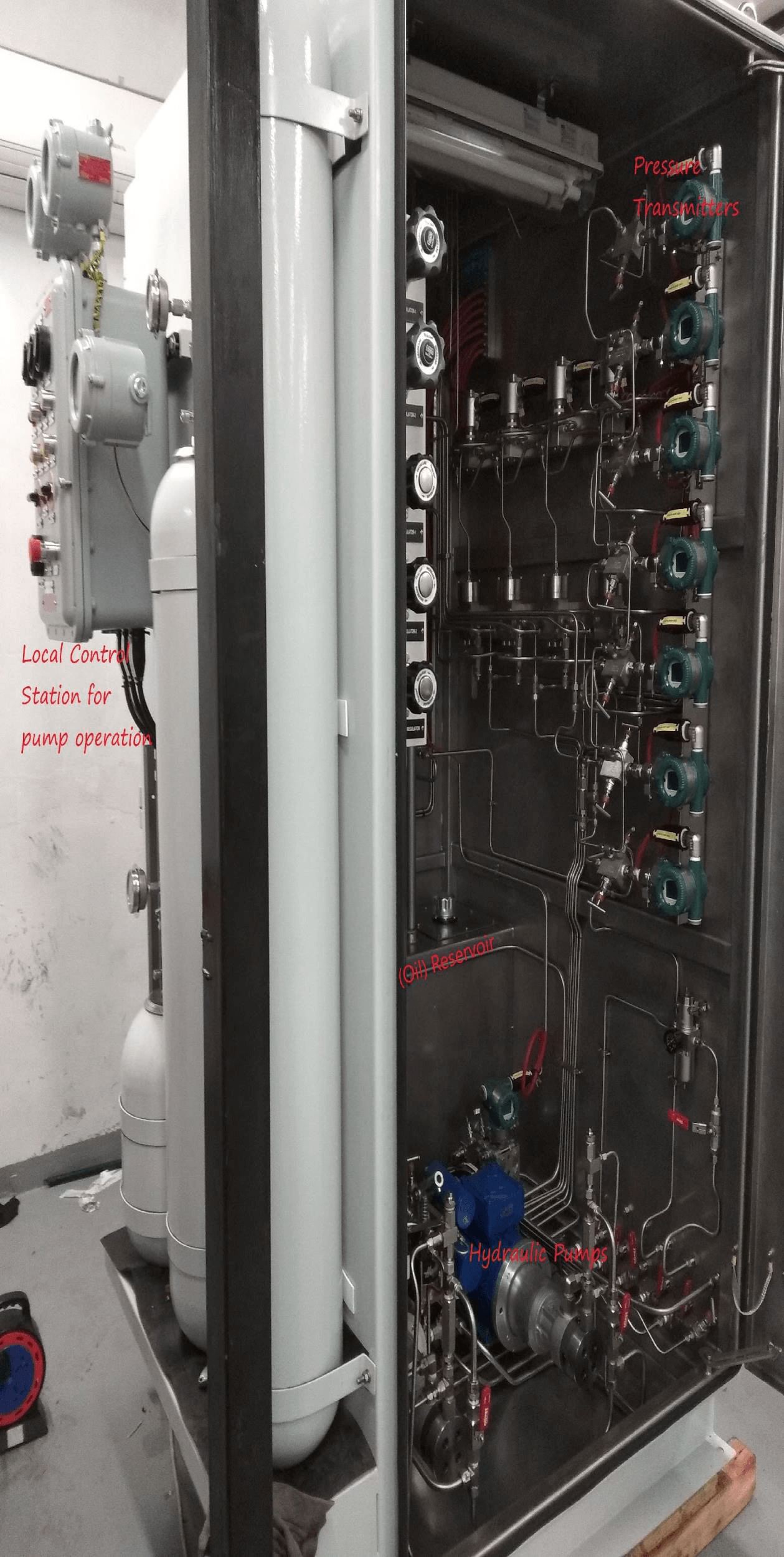
The redundant electrically powered hydraulic pumps are required to deliver higher hydraulic oil pressure. These pumps are common for all pressure headers. The Motor rating & pump capacity are selected to deliver the required pressure within 15 minutes.
Distance from the WHCP to the wellhead / hydraulic valves and the swept volume of actuators play an important role in sizing the pump and hydraulic tubing circuit.
Normally, duty/standby logic for pumps is implemented in PLC and interfaced via WHCP.
Oil Reservoir
The oil reservoir is a tank in which oil is stored and capacity is calculated based on hydraulic circuit sizing. It has an oil supply connection with pumps through strainers and return lines from valves are connected to the main hydraulic oil reservoir.
The oil reservoir is equipped with a flame arrester.
Regulators and Pressure Relief Valves
Regulators are used to provide regulated pressure to downstream oil headers which are used for each supply header.
e.g. if some valve requires higher operating pressure then this circuit will have a dedicated regulator and pressure relief valve.
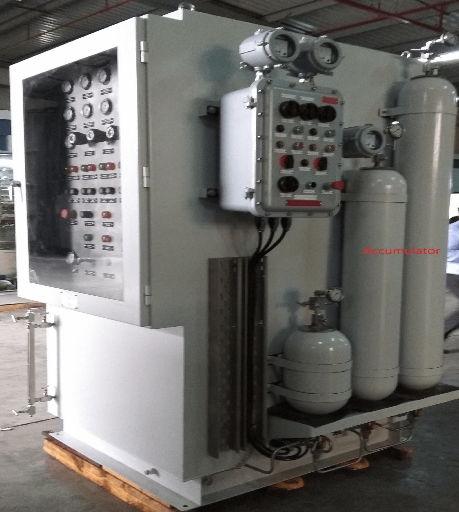
Accumulator
Accumulator sizing is done such that it allows two complete cycles of opening and closing of all wellhead valves without the requirement of pumping. Accumulators are precharged type,
Based on the isothermal compression and the isothermal or adiabatic expansion of the nitrogen precharge gas, the effective gas volume required is calculated.
Accumulators are placed in WHCP hydraulic circuits to supply pressure in case oil pressure is not available.
Hydraulic circuit
Depending upon the pressure requirement for valves, HP, MP, and LP headers are envisaged.
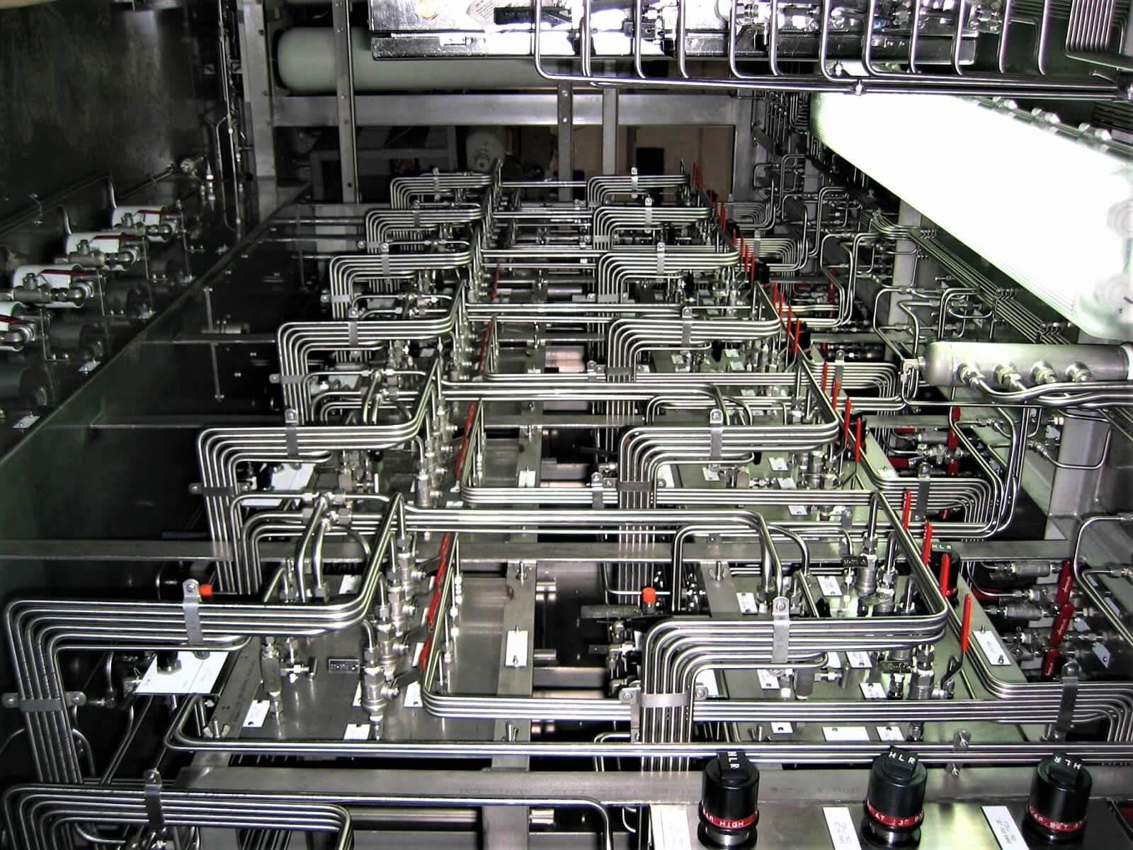
Hydraulic supply headers for the SSSVs, SSVs, UMVs, WVs, Choke valves are from WHCP. Interconnecting tubing will be installed at the site from WHCP to individual valves. The WHCP internal hydraulic circuit has a tube, tube fittings, check valves, isolation valves, quick exhaust valves, etc as per requirement.
Fusible plugs are used to hold hydraulic pressure and installed around the wellhead. In case of fire, the fusible plug melts and oil pressure will be released so that Christmas tree valves will be closed, and the well will be under a shutdown.
Sizing of the hydraulic lines between the WHCP and the valves is important for overall WHCP design.
Instrumentation interface
Pressure Transmitters and local pressure gauges are required on the Hydraulic headers for local monitoring and status indication of valves.
Level transmitter and level gauges are required to monitor reservoir level.
Solenoids are installed in hydraulic supply headers to valves. Once solenoids are energized hydraulic oil will pass through the solenoid and goes to valve actuators.
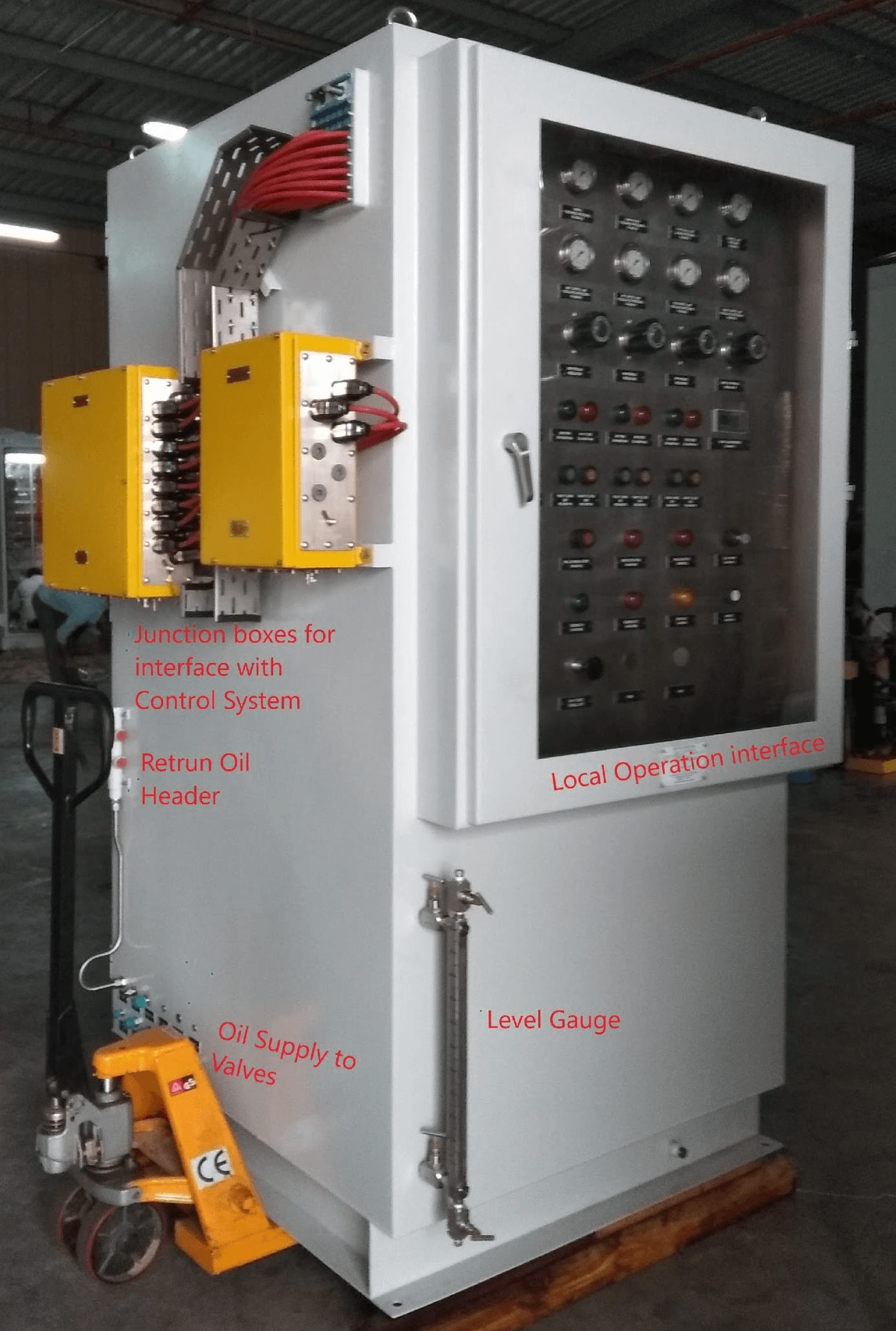
Pushbuttons/selector switches for the Christmas Tree valves local/test/remote operation SSSVs, SSVs, UMVs, WVs
Open/Close status indication lamps for the SSVs, SSSVs, UMVs, and WVs, etc.
Junction boxes for interconnection between WHCP and PLC/Control system (Pressure, Level, solenoids, or control of valves, start/stop of hydraulic pumps, status indication/local operation interfaces, etc)
Electrical interface
The electrical interface includes the power connection of Motors, starter control panel wiring, and control interface for remote operation of motors from PLC. This is implemented in an Electrical junction box where necessary relays, electrical wirings, voltmeters, ammeters, pushbuttons, lamps, MCBs, contactors, terminals, etc are installed.
Ground lugs should be provided for WHCP earthing.
Sizing of WHCP includes Accumulator volume calculation, oil reservoir tank capacity, pump capacity, and motor rating, tube sizing, tube thickness sizing. The number of hydraulic supplies, returns, cables, glands, plugs, panel cutouts has to be properly identified while designing.
Every component inside the panel should be suitable for the required hydraulic pressure operation and should meet the technical specification requirement of the project.
As you can see from photos of WHCP, you will notice that it is engineered such that a minimum interface is required at the site.
Photo courtesy: WT Petrotech
Author: Jatin Katrodiya
Read Next:
