Design a PLC program for the washing machine to control the water filling, agitate, spin, and drain process using the ladder logic.
Note: These PLC examples are for learning purposes to practice the ladder logic for beginners.
Washing Machine
Problem Statement:
Design a PLC ladder logic for the following application.
We are using one Push Button to Control the Filling, Agitate, Drain, Spin, and Buzzer.
When the Start Button is pressed, it starts filling the water for 10 seconds, then Agitate for 30 seconds, then Drain the water for 5 seconds, Spin the Drum for 10 seconds, and then Buzzer will be ON for 10 seconds.
Automation Training Courses
Instrumentation Tools provides you with the best automation training courses online for free of cost. You can enroll for the free courses on the “Automation Community” website.
This PLC video explains the washing machine programming example.
Inputs and Outputs
Digital Inputs:
Start Button: I0.0
Digital Outputs:
Filling: Q0.0
Agitation: Q0.1
Drain: Q0.2
Spin: Q0.3
Buzzer: Q0.4
PLC Programming
Program Explanation
We have used Normally Open Contact for the Start Button (I0.0).
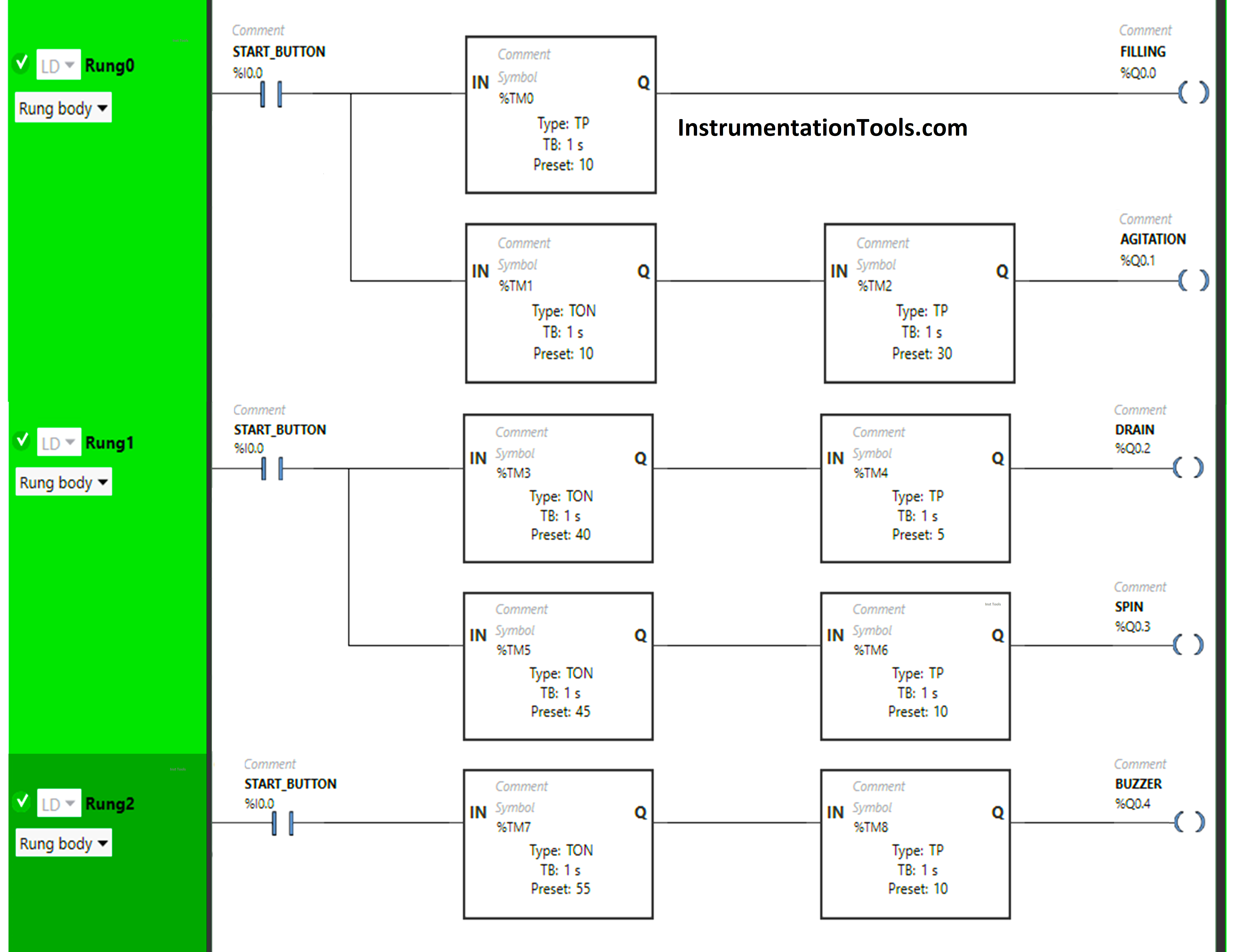
In Rung 0:
- Normally Open Contact is used for the Start Button (I0.0) to Turn ON the outputs Filling (Q0.1) and Agitate (Q0.1).
- Timer-type TP is used to Turn ON the output Filling (Q0.0) for a limited time.
- Timer-type TON is used to delay the turning ON time of the output Agitate (Q0.1) for some time.
- Timer-type TP is used to Turn ON the output Agitate (Q0.1) for a limited time.
In Rung 1:
- Normally Open Contact is used for the Start Button (I0.0) to Turn ON the outputs Drain (Q0.2) and Spin (Q0.3).
- Timer-type TON is used to delay the turning ON time of the output Drain (Q0.2) for some time.
- Timer-type TP is used to Turn ON the output Drain (Q0.2) for a limited time.
- Timer-type TON is used to delay the turning ON time of the output Spin (Q0.3) for some time.
- Timer-type TP is used to Turn ON the output Spin (Q0.3) for a limited time.
In Rung 2:
- Normally Open Contact is used for the Start Button (I0.0) to Turn ON the output Buzzer (Q0.4).
- Timer-type TON is used to delay the turning ON time of the output Buzzer (Q0.4) for some time.
- Timer-type TP is used to Turn ON the output Buzzer (Q0.4) for a limited time.
Simulation Results
We will simulate the PLC program and discuss the results. We may show the partial logic or rung in the respective test case instead of the complete program.
Watch the above video to see the PLC programming and simulations.
Rung 0:
When the Start Button (I0.0) is turned ON, the output Filling (Q0.0) turns ON ( Filling of water starts ) but for a limited time as Timer Function type TP is used to turn ON the Output Filling (Q0.0) or Filling of water for limited time. The time is set to 10 seconds.
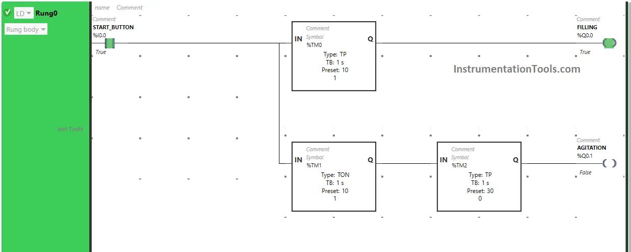
So after 10 seconds, the output Filling (Q0.0) will turn OFF, or after 10 seconds Filling of water finishes.
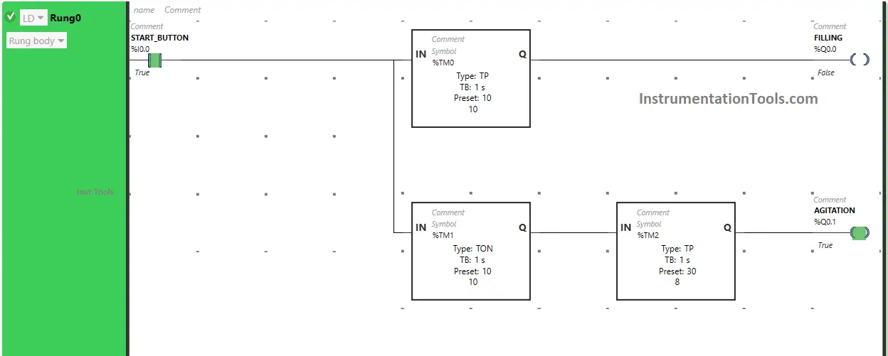
Also, when the Start Button (I0.0) is turned ON, the output Agitation (Q0.1) will turn ON after 10 seconds (i.e immediately after the output Filling (Q0.0) is turned OFF or after Filling of water is finished) because the Timer Function Block TON is used to delay the turning ON time of the output Agitation (Q0.1).
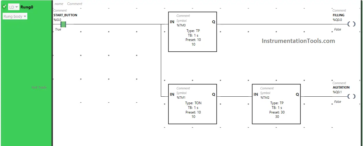
The time is set to 10 seconds. So after 10 seconds, the output Filling (Q0.1) will turn ON but for a limited time as Timer Function Block type TP is used to turn ON the output Agitation (Q0.1) for a limited time.
The time is set to 30 seconds. So after 30 seconds, the output Agitation (Q0.1) turns OFF.
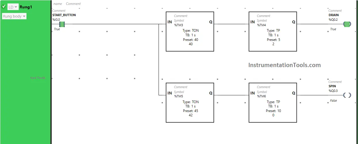
Rung 1:
When Start Button (I0.0) is turned ON, the output Drain (Q0.2) turns ON after 40 seconds or after 40 seconds Draining starts (i.e immediately after the output Agitation (Q0.1) is turned OFF) because Timer Function Block TON is used to delay the turning ON time of the output Drain (Q0.2).
The time is set to 40 seconds.
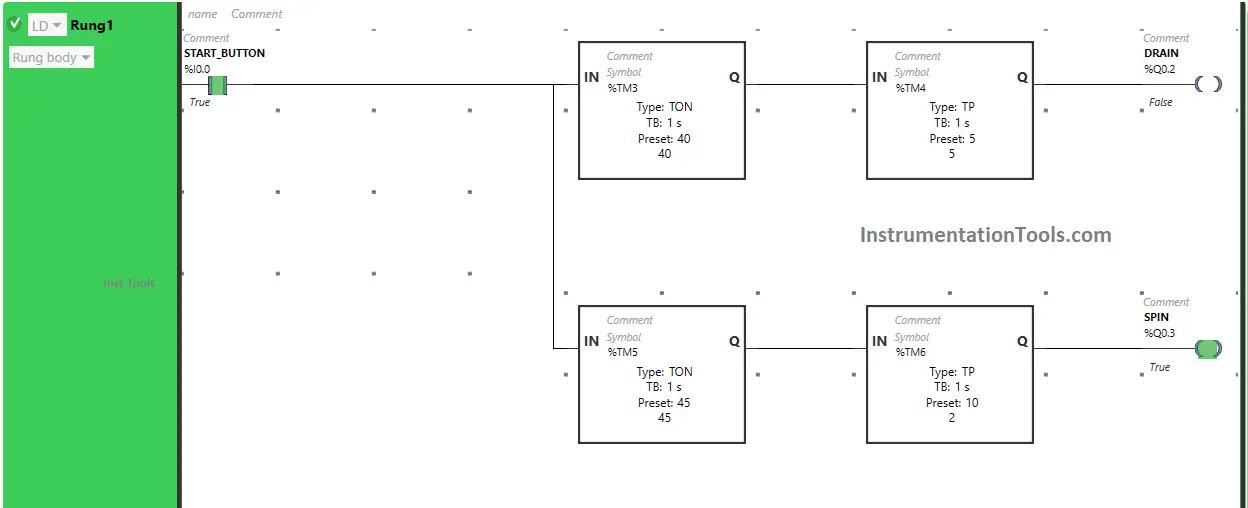
So after 40 seconds, the output Drain (Q0.2) will turn ON, or after 40 seconds Draining starts but for a limited time as Timer Function Block type TP is used to turn ON the output Drain (Q0.2) for a limited time. The time is set to 5 seconds.
So after 5 seconds, the output Drain (Q0.2) turns OFF, or after 5 seconds Draining finishes.
Also, When the Start Button (I0.0) is turned ON, the output Spin (Q0.3) will turn ON after 45 seconds, or after 45 seconds Spinning of clothes starts (i.e immediately after the output Drain (Q0.2) is turned OFF or after Draining is finished) because Timer Function Block TON is used to delay the turning ON time of the output Spin (Q0.3).
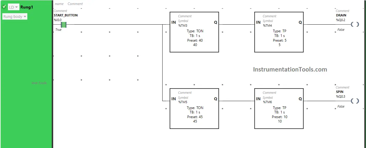
The time is set to 45 seconds.
After 45 seconds, the output Spin (Q0.3) will turn ON, or after 45 seconds Spinning of clothes starts but for a limited time as Timer Function Block type TP is used to turn ON the output Spin (Q0.3) for a limited time.
The time is set to 10 seconds. So after 10 seconds, the output Spin (Q0.3) turns OFF, or after 10 seconds Spinning finishes.
Rung 2:
When the Start Button (I0.0) is turned ON, the output Buzzer (Q0.4) turns ON after 55 seconds or after 55 seconds Buzzer starts (i.e immediately after the output Spin (Q0.3) is turned OFF or after Spinning is finished) because Timer Function Block TON is used to delay the turning ON time of the output Buzzer (Q0.4).
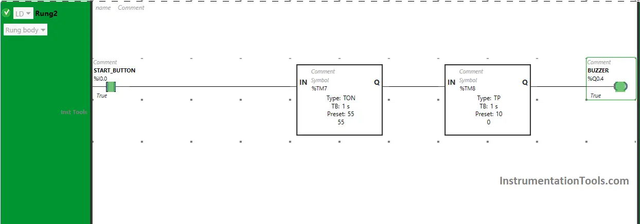
The time is set to 55 seconds.
After 55 seconds, the output Buzzer (Q0.4) will turn ON or after 55 seconds Buzzer starts but for a limited time as Timer Function Block type TP is used to turn ON the output Buzzer (Q0.4) for a limited time.
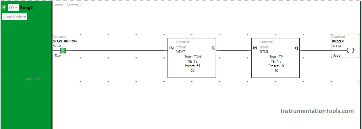
The time is set to 10 seconds. So after 10 seconds, the output Buzzer (Q0.4) turns OFF or after 10 seconds Buzzer stops.
If you liked this article, please subscribe to our YouTube Channel for PLC and SCADA video tutorials.
You can also follow us on Facebook and Twitter to receive daily updates.
Read Next:
- Advanced PLC Logic Programming
- PLC Program for Automatic Tank Mixing
- PLC Program for the Pump to fill the tank
- PLC Programming of Switch Program
- Quiz Program Logic using PLC Program