In this article, we shall learn about Vortex Flow Meters.
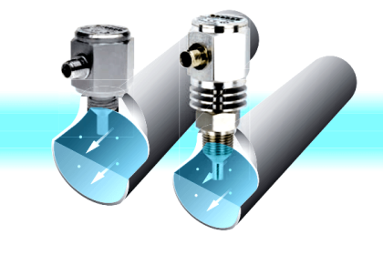
A vortex train is generated when a bluff body is placed in a pipe stream containing liquid or gas. This train consists of high and low-pressure areas which can be measured by a specially manufactured sensor.
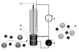
Vortex flow meters measure fluid velocity using a principle of operation referred to as the von Kármán effect, which states that when flow passes by a bluff body, a repeating pattern of swirling vortices is generated.
Vortex Flow Meters
In a Vortex flow meter, an obstruction in the flow path, often referred to as a shedder bar, serves as the bluff body.
The shedder bar causes process fluid to separate and form areas of alternating differential pressure known as vortices around the backside of the shedder bar.
The number of formations of these vortices depends on the flow rate, if we measure these vortices we can get the equivalent volumetric flow rate.
Also Read: Types of Vortex Sensors
Applications of Vortex Flow Meters
Vortex meters are commonly used in the following services:
- Cooling water.
- Process water.
- Light hydrocarbons where large turndown is required.
- Gas flow where large turndown is required.
Characteristics of Vortex Flow Meters
Vortex meters have the following characteristics:
- Wide rangeability (for Reynolds numbers above 10,000).
- An accuracy of 1 percent of the rate.
- A wide range of sizes.
- Linear output.
- Availability of pulse and analog outputs.
Limitations of Vortex Flow Meters
Vortex meters have the following limitations:
- A limited range of construction materials is available.
- Vortex meters are generally not suitable for slurries or high-viscosity liquids.
- Users cannot check calibration.
- Turbulent flow is required.
- Vortex meters have over range limitations.
- Strainers may be required.
- Vortex meters are affected by pulsating flow.
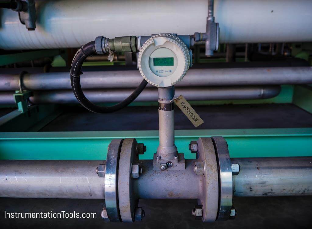
Installation
Vortex meters are installed directly in the process piping and are normally supported by the piping. They may be installed in any orientation. A vortex meter should be installed so that the meter body is not subjected to piping strain.
In liquid applications, the piping should be arranged so that the meter is kept full. Block and bypass valves should be provided when operating conditions do not permit shutdown.
Vortex meters are sometimes damaged during the start-up of new installations as a result of debris in the line. The line should be flushed and hydrostatically tested before the meter is installed.
Since the velocity profile is critical, it is imperative that gaskets not protrude into the flow stream when flanged meters are installed. Field calibration of vortex meters is limited to electrically spanning the converter or, on a pulse-output type, adjusting the scaling factor.
Vortex flow meters offer many advantages for flow measurement including easy installation without impulse lines, no moving parts to maintain or repair, less leak potential, and a wide flow turndown range. Vortex meters also offer very low power consumption, allowing for use in remote areas.
Additionally, Vortex meters are unique in that they can accommodate liquids, gasses, steam, and corrosive applications. Vortex flowmeters are also able to withstand high process pressures and temperatures.
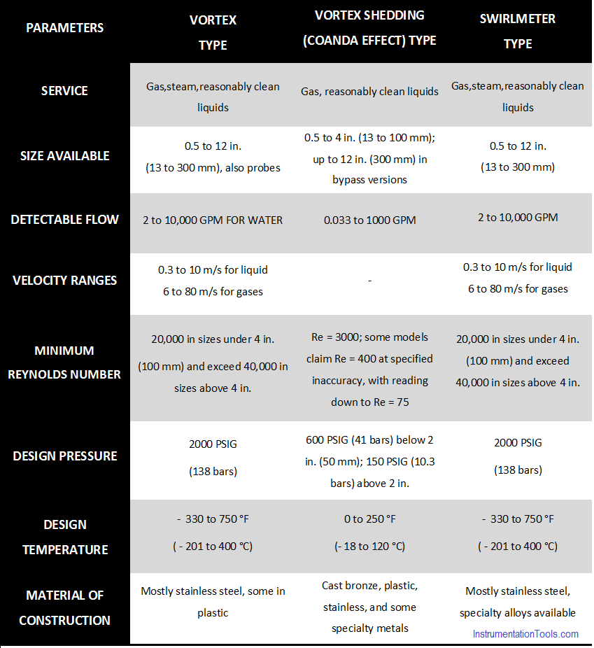
Vortex Meters Operating Conditions
Here we shall see which type of vortex meter to use in different operating conditions and services.
Interest to add any further points? Share with us through below comments section below.
Author: Kalpit Patel
If you liked this article, then please subscribe to our YouTube Channel for Instrumentation, Electrical, PLC, and SCADA video tutorials.
You can also follow us on Facebook and Twitter to receive daily updates.
Read Next:
- Wiring of Solenoid and PLC
- Orifice Plate Design Rules
- Level Instruments Specification
- Variable Area Flow Meter
- All About Turbine Meter