Inst ToolsInst ToolsInst Tools
  • Courses
  • Automation
    • PLC
    • Control System
    • Safety System
    • Communication
    • Fire & Gas System
  • Instrumentation
    • Design
    • Pressure
    • Temperature
    • Flow
    • Level
    • Vibration
    • Analyzer
    • Control Valve
    • Switch
    • Calibration
    • Erection & Commissioning
  • Interview
    • Instrumentation
    • Electrical
    • Electronics
    • Practical
  • Q&A
    • Instrumentation
    • Control System
    • Electrical
    • Electronics
    • Analog Electronics
    • Digital Electronics
    • Power Electronics
    • Microprocessor
  • Request
Search
  • Books
  • Software
  • Projects
  • Process
  • Tools
  • Basics
  • Formula
  • Power Plant
  • Root Cause Analysis
  • Electrical Basics
  • Animation
  • Standards
  • 4-20 mA Course
  • Siemens PLC Course
Reading: Valve Actuator Bench Set
Share
Font ResizerAa
Inst ToolsInst Tools
Font ResizerAa
  • Courses
  • Design
  • PLC
  • Interview
  • Control System
Search
  • Courses
  • Automation
    • PLC
    • Control System
    • Safety System
    • Communication
    • Fire & Gas System
  • Instrumentation
    • Design
    • Pressure
    • Temperature
    • Flow
    • Level
    • Vibration
    • Analyzer
    • Control Valve
    • Switch
    • Calibration
    • Erection & Commissioning
  • Interview
    • Instrumentation
    • Electrical
    • Electronics
    • Practical
  • Q&A
    • Instrumentation
    • Control System
    • Electrical
    • Electronics
    • Analog Electronics
    • Digital Electronics
    • Power Electronics
    • Microprocessor
  • Request
Follow US
All rights reserved. Reproduction in whole or in part without written permission is prohibited.
Inst Tools > Blog > Control Valves > Valve Actuator Bench Set

Valve Actuator Bench Set

Last updated: August 12, 2020 11:42 am
Editorial Staff
Control Valves
No Comments
Share
5 Min Read
SHARE

Valve actuators provide force to move control valve trim. For precise positioning of a control valve, there must be a calibrated relationship between applied force and valve position.

Most pneumatic actuators exploit Hooke’s Law to translate applied air pressure to valve stem position.

F = kx

Where,
F = Force applied to spring in newtons (metric) or pounds (British)
k = Constant of elasticity, or “spring constant” in newtons per meter (metric) or pounds per foot (British)
x = Displacement of spring in meters (metric) or feet (British)

Hooke’s Law is a linear function, which means that spring motion will be linearly related to applied force from the actuator element (piston or diaphragm).

Since the working area of a piston or diaphragm is constant, the relationship between actuating fluid pressure and force will be a simple proportion (F = PA).

By algebraic substitution, we may alter Hooke’s Law to include pressure and area:

F = kx
PA = kx

Solving for spring compression as a function of pressure, area, and spring constant:

x = PA/k

Valve Actuator Bench Set

Valve Actuator Bench Set

When a control valve is assembled from an actuator and a valve body, the two mechanisms must be coupled together in such a way that the valve moves between its fully closed and fully open positions with an expected range of air pressures. A common standard for pneumatic control valve actuators is 3 to 15 PSI.

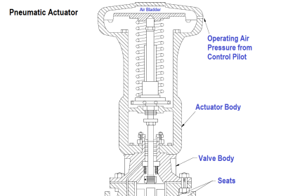
There are really only two mechanical adjustments that need to be made when coupling a pneumatic diaphragm actuator to a sliding-stem valve: the stem connector and the spring adjuster.

The stem connector mechanically joins the sliding stems of both actuator and valve body so they move together as one stem. This connector must be adjusted so neither the actuator nor the valve trim prevents full travel of the valve trim:

Control Valve Stroking

Note how the plug rests fully on the seat when the valve is closed, and how the travel indicator indicates fully open at the point where the actuator diaphragm nears its fully upward travel limit. This is how things should be when the stem connector is properly adjusted.

If the stem connector is set with the actuator and valve stems spaced too far apart (i.e. the total stem length is too long), the actuator diaphragm will bind travel at the upper end and the valve plug will bind travel at the lower end. The result is a valve that cannot ever fully open:

Bench Set of Control Valve Actuator

A control valve improperly adjusted in this manner will never achieve full-flow capacity, which may have an adverse impact on control system performance.

If the stem connector is set with the actuator and valve stems too closely coupled (i.e. the total stem length is too short), the actuator diaphragm will bind travel at the lower end and the valve plug will bind travel at the upper end.

The result is a valve that cannot ever fully close:

Control Valve Bench Set

This is a very dangerous condition: a control valve that lacks the ability to fully shut off. The process in which this valve is installed may be placed in jeopardy if the valve lacks the ability to stop the flow of fluid through it!

Once the stem length has been properly set by adjusting the stem connector, the spring adjuster must be set for the proper bench set pressure. This is the pneumatic signal pressure required to lift the plug off the seat.

For an air-to-open control valve with a 3 to 15 PSI signal range, the “bench set” pressure would be 3 PSI.

Bench set is a very important parameter for a control valve because it establishes the seating force (seat load) of the plug against the seat when the valve is fully closed.

Proper seating pressure is critical for tight shut-off, which carries safety implications in some process services. Consult the manufacturer’s instructions when adjusting the bench set pressure for any sliding-stem control valve.

These instructions will typically guide you through both the stem connector and the spring adjuster procedures, to ensure both parameters are correctly set.

Also Read : Control Valve Parts

Don't Miss Our Updates
Be the first to get exclusive content straight to your email.
We promise not to spam you. You can unsubscribe at any time.
Invalid email address
You've successfully subscribed !

Continue Reading

What is a Boiler Pressure Relief Valve?
What is Travel Stop in Control Valve?
What is Flapper Nozzle System ?
3 Port 2 Position Direct Acting Solenoid Valve Working Principle
Safety Relief Valve Questions & Answers
Difference between BDV and PSV
Share This Article
Facebook Whatsapp Whatsapp LinkedIn Copy Link
Share
Leave a Comment

Leave a Reply Cancel reply

Your email address will not be published. Required fields are marked *

Stay Connected

128.3kFollowersLike
69.1kFollowersFollow
210kSubscribersSubscribe
38kFollowersFollow

Categories

Explore More

Calculate Control Valve Stem Position
Metal Seated Valves and Soft Seated Valves : Differences
Face to Face Dimension of Control Valve
What is a Electric Motor Actuator ?
Short Notes on Different Valve Types
Self-Actuated Valves, Pneumatic & Hydraulic Actuators
Difference between RTJ and T&G Flange Facings
Basics of Valves Interview Questions & Answers

Keep Learning

Difference between Globe Valve and Gate Valve

Difference between Globe Valve and Gate Valve ?

Motor Operated Valve Problems and Troubleshooting

Motor Operated Valve Problems and Troubleshooting

On-OFF Valve Animation

What is ON/OFF Valve ?

Two SOV Connections

Two Solenoid Valves Working Principle

Opposite Acting Valves

What is Split Range Control Loop ?

Valve Interlock

Valve Interlock

Control valve performance with constant pressure

Control Valve Performance with Constant Pressure

What is a Spool valve

What is a Spool Valve? – Types, Configurations, Applications

Learn More

Business Skills Every Engineer Needs

Business Skills Every Engineer Needs

induction motor torque versus speed

Induction Motor Torque Versus Slip

failure rate of a component - 1

Failure rate and MTBF of Safety Instrumented Systems

Difference Between NEMA and IEC Motors

Difference Between NEMA and IEC Motors?

capacitance probe

Capacitance Level Measurement Working Principle

DeadWeight Tester

DeadWeight Tester Questions

Difference Between RS232 and RS485

Difference Between RS232 and RS485

Digital Electronics Objective Questions

Digital Electronics Objective Questions – Set 9

Menu

  • About
  • Privacy Policy
  • Copyright

Quick Links

  • Learn PLC
  • Helping Hand
  • Part Time Job

YouTube Subscribe

Follow US
All rights reserved. Reproduction in whole or in part without written permission is prohibited.
Welcome Back!

Sign in to your account

Username or Email Address
Password

Lost your password?