Ethernet is the fastest mode of communication in networking systems. When you design an Ethernet network, you must know how long you can lay the cables. It should not be like you are just laying the cables and do not know what is the maximum distance it can cover. Because, exceeding maximum distance can result in loss of data, low network speeds, and increasing network latency. So, in this post, we will see the various types of cable lengths that can be used in Ethernet networks.
Ethernet Cable Categories
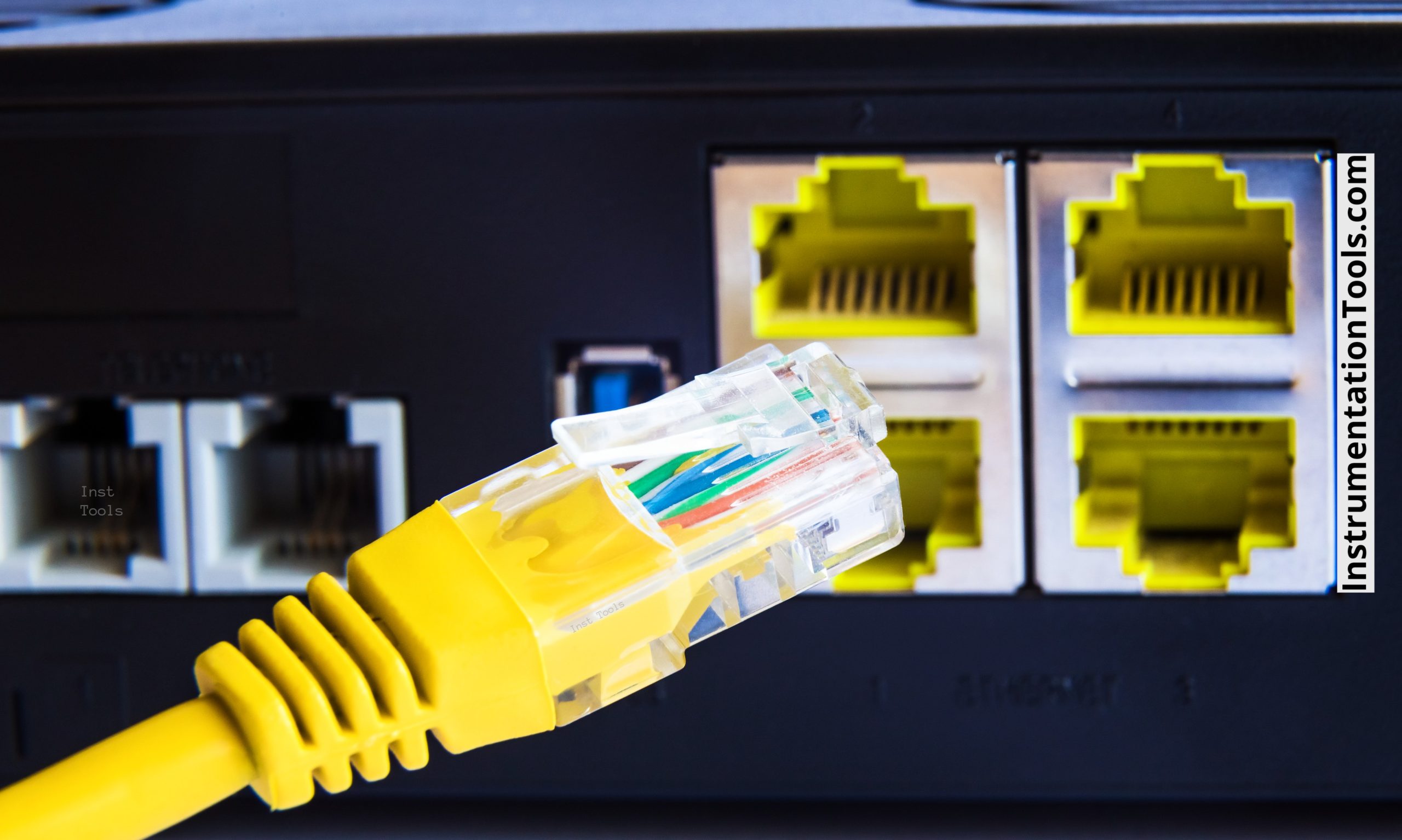
First of all, it is to be known that Ethernet communication can be done through two modes – standard and optical fiber. The standard one is the one where you can use it for shorter distances and the optical fiber is the one where you can use it for longer distances (ranging in km). Optical fiber is a technology where data is transmitted in the form of light, and as the speed of light is very fast, it can cover longer distances.
Types of Standard Ethernet Cables
The types of standard Ethernet cables are as below (CAT is nothing but a category):
- CAT-1 (unshielded twisted pair cable; outdated, was used for analog voice communication)
- CAT-2 (extension of CAT-1; speed little higher than CAT-1 which is up to 4 Mbps)
- CAT-3 (four twisted pair cables, supporting 10 Mbps speed)
- CAT-4 (extension of CAT-3; speed little higher than CAT-3 which is up to 16 Mbps)
- CAT-5 (twisted pair cable; speed of up to 100 Mbps)
- CAT-6 (extension of CAT-5; speed higher than CAT-5 which is up to 1 Gbps. It is possible due to more shielding and pairs to reduce crosstalk)
- CAT-7 (The speed is similar to CAT-6, but has a greater bandwidth)
- CAT-8 (speed of up to 40 Gbps)
Types of Standard Optical Fiber Cables
The types of standard optical fiber cables are as below:
- 100 Base FX (Fast Ethernet at 100 Mbps)
- 1000 Base SX (Gigabit Ethernet at 1000 Mbps; SX means short reach)
- 1000 Base LX (Gigabit Ethernet at 1000 Mbps; LX means long reach)
- 1000 Base BX (Gigabit Ethernet at 1000 Mbps; BX means bidirectional transmission)
- 1000 Base EX (Gigabit Ethernet at 1000 Mbps; EX means extend reach)
Let us clear some general terms related to our topic before proceeding further:
- The number before base specifies the maximum speed that the optical fiber cable can carry.
- Single-mode fibers allow light to pass in only one direction, so they have a smaller physical core size. This makes it suitable for high-speed data transmission over longer distances with less noise interference. Multimode fibers allow very paths for a light to pass, so they have a bigger physical core size. This makes it suitable for shorter distances as the noise interference is a bit higher and the bandwidth becomes lower. Multimode is cheaper than single mode due to lower accuracy and less distance covered. Have a read at this post for a deeper understanding. Choosing the right cable length will first require you to choose between single mode and multi-mode cables.
- Standard Ethernet cables come in a maximum of 8-core (8 wires inside a single cable) form. So, be it any CAT type, the maximum number of stranded, twisted / untwisted, shielded wires in a single cable will not exceed 8. You can see how a standard RJ45 port used widely has only 8 wire pins in it.
Ethernet Cable Lengths
Now that we know what the types of Ethernet cables are, let us see how much the maximum distance they can cover. Remember some important points below related to cable length before digging further:
- Proper shielding inside the cable allows data to flow efficiently and with less interruption from outside noise. Due to this, it can also cover longer distances.
- If the temperature around the cable is high, it is recommended to use shorter length cables. This is because temperature has an effect on data rate and bandwidth of Ethernet communication.
- If you are not using optical fiber and still want to increase the length using standard CAT cables, it can be done with the help of repeaters, or Ethernet extenders. But, the best performance for longer distances is achieved through optical fiber communication.
- Proper routing of cable laying should be planned before ordering final size, otherwise which would result in unwanted data wastage and reduced speeds.
- It is a myth that when you use network switches, your length can be increased. Consider two end points communicating on Ethernet, at a distance of 50 meters between them. There is a network switch after 40 meters. It will not be like you can increase the total distance to 80 meters. This is because the design length was 50 meters, and the switch just allows provision to add some more devices to the network. It does not aid in increasing distance.
Ethernet Cables Distance
Now, the standard distances that the Ethernet cables can cover are:
- CAT – All the CAT-type cables or the standard ones can cover only a distance of 100 m.
- 100 Base FX – Up to 2 kms.
- 1000 Base SX – Up to 275 m (generally uses multi-mode).
- 1000 Base LX – Up to 10 kms (can be used in both single mode and multi-mode).
- 1000 Base EX – Up to 40 kms (generally uses single-mode).
- 1000 Base ZX – Up to 80 kms (generally uses single-mode).
In this way, we saw the various types of cable lengths used in Ethernet networks.
Read Next:
- Difference Between TCP and UDP
- What is Rapid Spanning Tree Protocol?
- Network Switch Requirement in SCADA
- Network Switch Port Allocation Details
- Facts About RS485 Industrial Network
