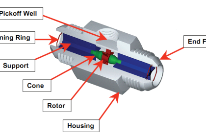
The Transit Time flow meter measures the time it takes for an ultrasonic signal transmitted from one transducer to cross a pipe and be received by a second transducer.
Upstream and downstream time measurements are compared. With no flow, the transit time would be equal in both directions.
With flow, sound will travel faster in the direction of flow and slower against the flow.
Transit Time Flow Meter

Very accurate timing circuits are required but 1% accuracy is quite typical when the transducers can be mounted on a pipe section with evenly distributed flow.
Because the ultrasonic signal must cross the pipe to a receiving transducer, the fluid must not contain a significant concentration of bubbles or solids (less than 2%).
Otherwise, the high-frequency sound will be attenuated and too weak to traverse the pipe.
Applications include potable water, cooling water, water/glycol solutions, hydraulic oil, fuel oils, and chemicals.
Transit Time transducers typically operate in the 1-2 MHz frequencies. Higher frequency designs are normally used in smaller pipes and lower frequencies for large pipes up to several meters in diameter.
Source: Greyline Instruments
If you liked this article, then please subscribe to our YouTube Channel for Instrumentation, Electrical, PLC, and SCADA video tutorials.
You can also follow us on Facebook and Twitter to receive daily updates.
Read Next:
- Paddle wheel flow meters
- Flow Meter Installation Guidelines
- Turbine Meter Troubleshooting
- What is a Coriolis flow meter?
- Flow Measuring Questions