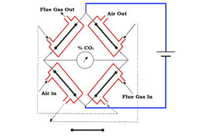
One way to improve on the single-beam analyzer design is to split the light beam into two equal halves, then pass each half-beam through its own cell. Only one of these cells will hold the process gas to be analyzed – the other cell is sealed, containing a “reference” gas such as nitrogen that absorbs no infrared light. At the end of each cell we will place a matched pair of thermopile detectors, connecting these detectors in series-opposing fashion so equal voltages will cancel:
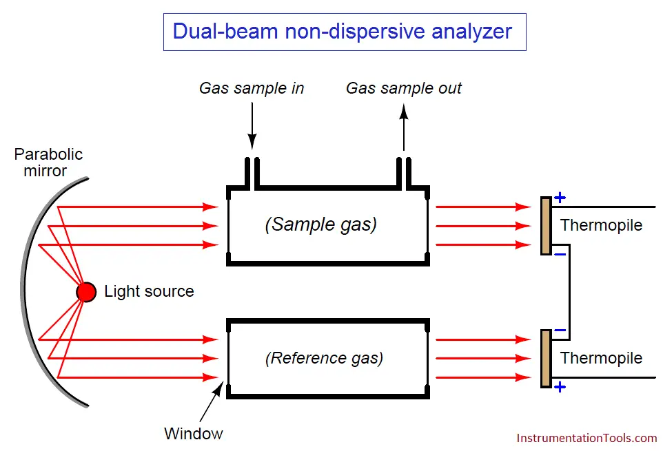
Let us perform some “thought experiments” on this apparatus to explore its behavior. Imagine the sample gas being a non-absorber of infrared light just like the reference gas. In this virtual experiment, the opposed detector pair will generate no voltage signal because each of the two detectors receives the same (full) amount of incident light.
Next, we will alter one of the variables in our “thought experiment” to see what difference that variable makes. Here, we imagine the sample containing some concentration of an infrared-absorbing gas while the reference gas continues to absorb no light. Now, the two thermopile detectors will receive differing intensities of infrared light, causing the series-opposed pair to be out of balance, generating a net voltage signal we can measure as an indication of light-absorbing gas concentration.
The addition of a reference gas chamber and second thermopile detector completely eliminates the ambient temperature problem seen in the single-detector apparatus. If the analyzer’s temperature happens to rise or fall, the voltages output by both thermopiles will rise and fall equally, canceling each other out so that the only voltage produced by the series-opposing pair will be that produced by differences in received light intensity.
The dual-detector design also eliminates the problem of “zero drift” as the light source ages. As time progresses and the light source becomes dimmer, both detectors see less light than before. Since the detector pair measures the difference between the two light beam intensities, any degradation common to both beams will be ignored.
Another detector problem still remains, in that an imbalance will develop if one detector happens to “drift” in voltage apart from the other, so they are no longer in perfect counter-balance even with the same received light intensities. This might happen if one of the thermopiles experiences greater ambient temperature than the other, perhaps due to convective heat transfer from hot process sample gas in the nearby sample cell and not the reference cell. An ingenious solution to this problem is to insert a spinning metal “chopper” wheel in the path of both light beams, causing the light beams to pulse through the sample and reference cells at a low frequency (typically a few pulses per second):
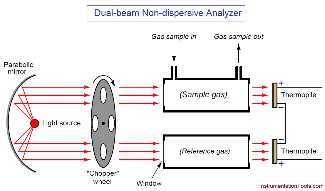
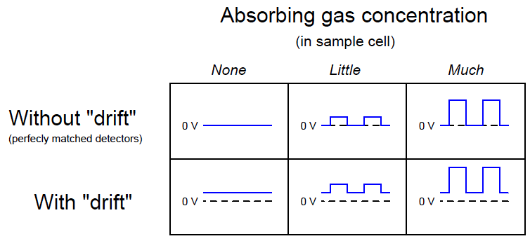
The effect of the “chopper” is to make the detector assembly output a pulsating (“AC”) voltage signal rather than a steady voltage signal. The peak-to-peak amplitude of this pulsating signal represents the difference in light intensity between the two detectors, but any “drift” will manifest itself as a constant or very slowly-changing (“DC”) bias voltage. The following table illustrates the detector assembly signal for three different gas concentrations (none, little, and much) both with and without a mis-match in detector signals due to thermal drift:
This DC bias voltage is very easy to filter in the amplifier section of the analyzer. All we need is capacitive coupling between the detector assembly and the amplifier, and the amplifier will never “see” the DC bias voltage:
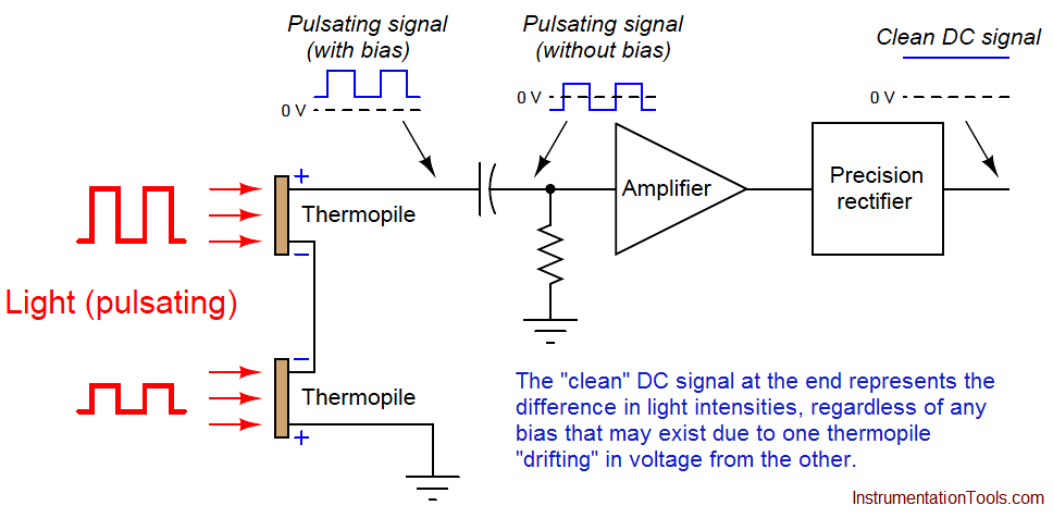
With the detector assembly producing an “AC” (pulsing) signal instead of a “DC” signal, and by using capacitive coupling to the amplifier, the electronic circuit responds only to changes in the amplitude of the AC waveform and not to its DC bias. This means the analyzer will only respond to changes in detector temperature resulting from changes in light absorbance (i.e. gas concentration), and not from any other factor such as ambient temperature drift. In other words, since the amplifier has been built to only amplify pulsing signals, and the only thing pulsing in this instrument is the light, the electronics will only measure the effects generated by the light, rejecting all other stimuli.
Despite the design improvement of the chopper wheel and AC-coupled amplifier circuit, another significant problem remains with this analyzer: it is still a non-selective instrument. Any light absorbing gas entering the sample cell will cause the detector pair to generate a signal regardless of the type of gas, because the thermopile detectors respond to a broad range of light wavelengths. While this may suffice for some industrial applications, it will not for most where a mixture of light-absorbing gases coexist. What we need is a way to make this instrument selective to just one type of gas, in order that it be a useful analyzer in a wider variety of process applications.
Also Read : Non-Dispersive Analyzers