Inst ToolsInst ToolsInst Tools
  • Courses
  • Automation
    • PLC
    • Control System
    • Safety System
    • Communication
    • Fire & Gas System
  • Instrumentation
    • Design
    • Pressure
    • Temperature
    • Flow
    • Level
    • Vibration
    • Analyzer
    • Control Valve
    • Switch
    • Calibration
    • Erection & Commissioning
  • Interview
    • Instrumentation
    • Electrical
    • Electronics
    • Practical
  • Q&A
    • Instrumentation
    • Control System
    • Electrical
    • Electronics
    • Analog Electronics
    • Digital Electronics
    • Power Electronics
    • Microprocessor
  • Request
Search
  • Books
  • Software
  • Projects
  • Process
  • Tools
  • Basics
  • Formula
  • Power Plant
  • Root Cause Analysis
  • Electrical Basics
  • Animation
  • Standards
  • 4-20 mA Course
  • Siemens PLC Course
Reading: Complete PLC Project: Traffic Light Auto and Manual Automation
Share
Font ResizerAa
Inst ToolsInst Tools
Font ResizerAa
  • Courses
  • Design
  • PLC
  • Interview
  • Control System
Search
  • Courses
  • Automation
    • PLC
    • Control System
    • Safety System
    • Communication
    • Fire & Gas System
  • Instrumentation
    • Design
    • Pressure
    • Temperature
    • Flow
    • Level
    • Vibration
    • Analyzer
    • Control Valve
    • Switch
    • Calibration
    • Erection & Commissioning
  • Interview
    • Instrumentation
    • Electrical
    • Electronics
    • Practical
  • Q&A
    • Instrumentation
    • Control System
    • Electrical
    • Electronics
    • Analog Electronics
    • Digital Electronics
    • Power Electronics
    • Microprocessor
  • Request
Follow US
All rights reserved. Reproduction in whole or in part without written permission is prohibited.
Inst Tools > Blog > PLC Tutorials > Complete PLC Project: Traffic Light Auto and Manual Automation

Complete PLC Project: Traffic Light Auto and Manual Automation

Master the Traffic Light System's Auto and Manual Automation modes and complete PLC project for traffic management solutions.

Last updated: June 30, 2025 6:38 am
Editorial Staff
PLC Tutorials
No Comments
Share
7 Min Read
SHARE

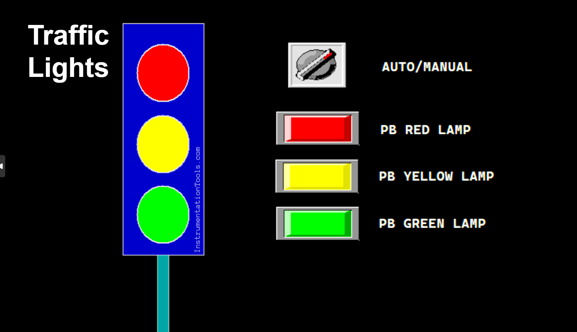
This article will discuss the complete PLC project for the Traffic Light System that can be run in Auto or Manual mode using the XG-5000 software. When the system is running in Auto mode, the Green, Yellow, and Red lights will turn ON alternately at different time intervals as designed for our application. When the system is running in Manual mode, each light can only be turned ON or OFF using the respective buttons.

Contents
Program ObjectiveTraffic Light Auto and Manual AutomationProgram I/O DetailsComplete PLC Project

Program Objective

PLC project for traffic signals automation

The Traffic Light Sequence as follows:

a. Auto Mode:

In the auto mode, the Selector Switch position needs to be changed to “Auto” mode.

  • Initial Cycle: When the program is started in automatic mode, the green lamp will be ON first.  
  • Color Change Sequence: After the Green lamp is ON for 5 seconds, the Yellow lamp will turn ON for 3 seconds. Next, the Red lamp will turn ON for 4 seconds.
  • Cycle Repetition: After the Red lamp turns OFF, the cycle will repeat from the beginning, with the Green lamp turning ON again for 5 seconds, and so on.
  • Repeating Process: This color changing process will continue to repeat automatically as long as the program is Run in this mode and will stop if the “Stop” button is Pressed.

b. Manual Mode:

In this mode, the Selector Switch needs to be changed to the “Manual” mode, and each lamp can be turned ON or OFF individually using a button.

There are three buttons, each controlling one lamp (Green, Yellow, and Red).

Traffic Light Auto and Manual Automation
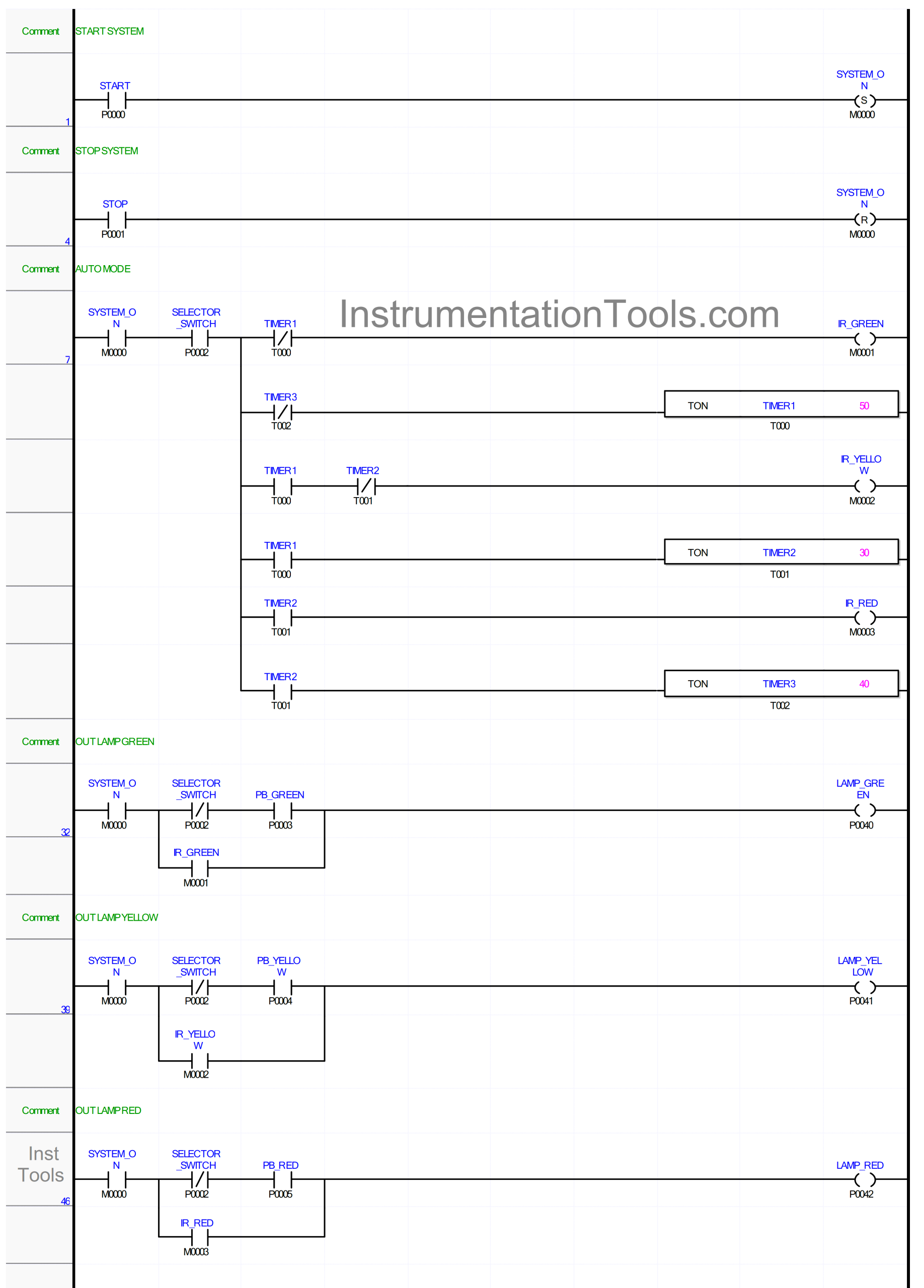
Complete PLC Project - Traffic Light Auto and Manual Automation

Program I/O Details

S.No.CommentInput (I)Output(Q)Memory BitTimer
 1STARTP0000   
 2STOPP0001   
 3SELECTOR_SWITCHP0002   
 4PB_GREENP0003   
 5PB_YELLOWP0004   
 6PB_REDP0005   
 7LAMP_GREEN P0040  
 8LAMP_YELLOW P0041  
 9LAMP_RED P0042  
 10TIMER1   T000
 11TIMER2   T001
 12TIMER3   T002
 13SYSTEM_ON  M0000 
 14IR_GREEN  M0001 
 15IR_YELLOW  M0002 
 16IR_RED  M0003 

Complete PLC Project

Traffic light PLC programming tutorial

RUNG 1 (START SYSTEM)

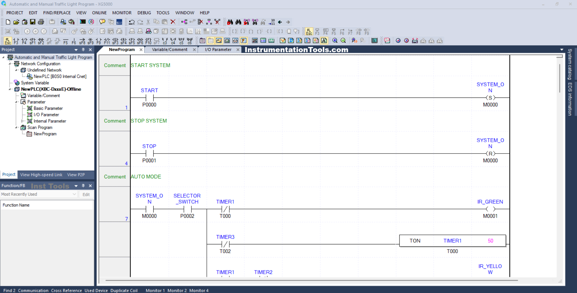
In this Rung, the memory bit SYSTEM_ON (M0000) will be in the HIGH state when the START button (P0000) is Pressed. Because it uses the SET Coil Instruction, the memory bit SYSTEM_ON (M0000) will remain in the HIGH state even though the START (P0000) button has been Released.

RUNG 4 (STOP SYSTEM)

In this Rung, the memory bit SYSTEM_ON (M0000) will be in the LOW state if the STOP (P0001) button is Pressed. Because it uses the RESET Coil Instruction, the memory bit SYSTEM_ON (M0000) will remain in the HIGH state even though the STOP (P0001) button has been Released.
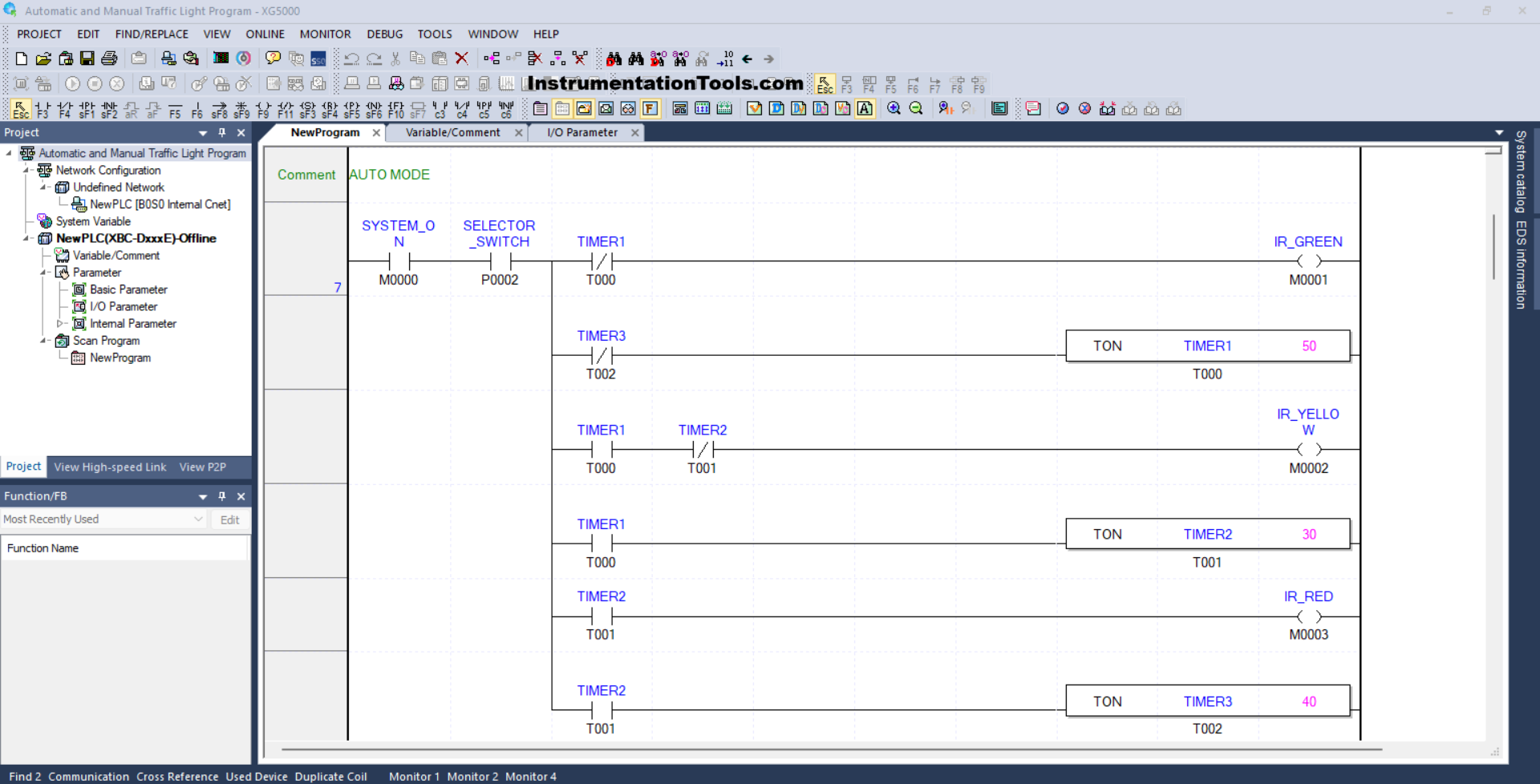
Automatic and manual traffic light control using PLC

RUNG 7 (AUTO MODE)

In this Rung, when the NO contact of memory bit SYSTEM_ON (M0000) and the NO contact of Selector Switch SELECTOR_SWITCH (P0002) are in the HIGH state, then the memory bit IR_GREEN (M0001) will be in the HIGH state and the timer TIMER1 (T000) will Start counting up to 5 seconds.

When Timer TIMER1 (T000) has finished counting, the memory bit IR_GREEN (M0001) will be in the LOW state, and the memory bit IR_YELLOW (M0002) will be in the HIGH state. Timer TIMER2 (T001) will Start counting up to 3 seconds.

When Timer TIMER2 (T001) has finished counting, the memory bit IR_YELLOW (M0002) will be in the LOW state, and the memory bit IR_RED (M0003) will be in the HIGH state. Timer TIMER3 (T002) will Start counting up to 4 seconds.

Next, when Timer TIMER3 (T002) has finished counting, Timer TIMER1 (T000) will be Reset due to the interlock of Timer TIMER3 (T002).
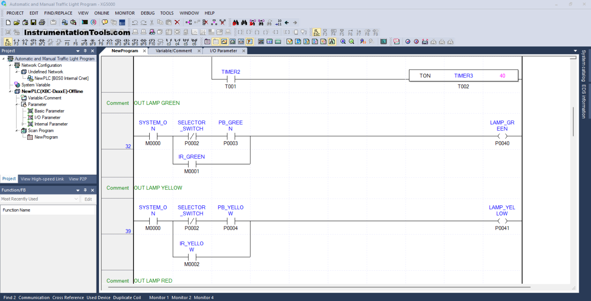
PLC based smart traffic management system

RUNG 32 (OUT LAMP GREEN)

In this Rung, when the NO contact of memory bit SYSTEM_ON (M0000) is in the HIGH state, the NC contact of Selector Switch SELECTOR_SWITCH (P0002) is in the LOW state and the PB_GREEN (P0003) button has been Pressed, then the LAMP_GREEN (P0040) output will be ON. .

Or, if the NO contact of the memory bit IR_GREEN (M0001) is in the HIGH state, then the LAMP_GREEN (P0040) output will be ON.

RUNG 39 (OUT LAMP YELLOW)

In this Rung, when the NO contact of memory bit SYSTEM_ON (M0000) is in the HIGH state, the NC contact of Selector Switch SELECTOR_SWITCH (P0002) is in the LOW state, and the PB_YELLOW (P0004) button has been Pressed, then the output LAMP_YELLOW (P0041) will be ON.

Or, if the NO contact of memory bit IR_YELLOW (M0002) is in the HIGH state, then the LAMP_YELLOW (P0041) output will be ON.
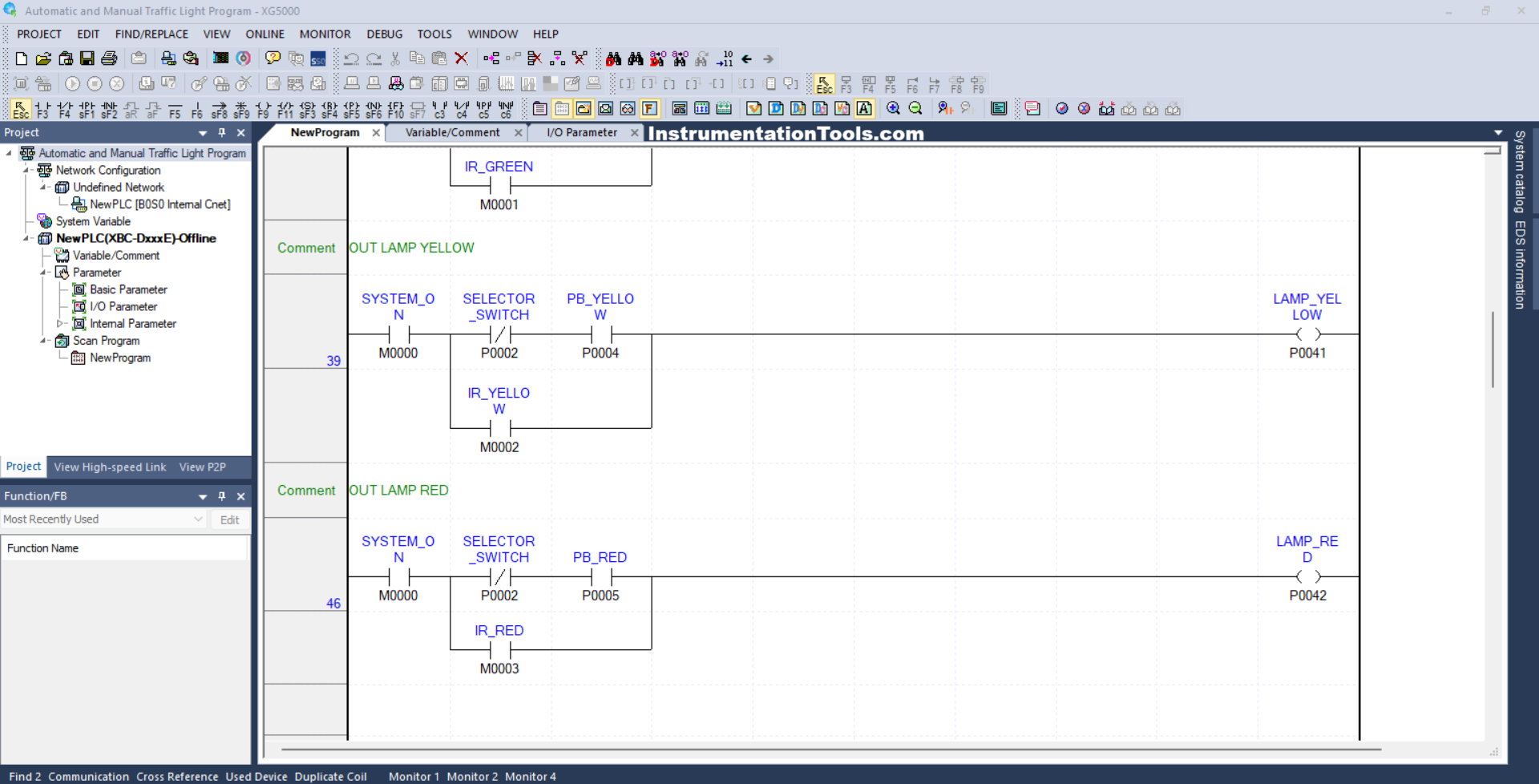
Complete PLC project for traffic control system

RUNG 46 (OUT LAMP RED)

In this Rung, when the NO contact of memory bit SYSTEM_ON (M0000) in the HIGH state, the NC contact of Selector Switch SELECTOR_SWITCH (P0002) in the LOW state and the PB_ RED (P0005) button has been Pressed, the output LAMP_ RED (P0042) will be to be ON.

Or, if the NO contact of memory bit IR_RED (M0003) is in the HIGH state, then the LAMP_RED (P0042) output will be ON.

Read Next:
  • PLC Program for Traffic Light Sequence
  • Siemens LOGO PLC Programming Course
  • Functional Block Diagram of Studio 5000
  • Why is 24 Volts Commonly used in PLC?
  • Functional Block Diagram for Traffic Lights

Don't Miss Our Updates
Be the first to get exclusive content straight to your email.
We promise not to spam you. You can unsubscribe at any time.
Invalid email address
You've successfully subscribed !

Continue Reading

Types of Failures in Industrial Automation Systems
I&C Engineer Roles & Responsibilities – Instrumentation Design
Comparison of Control Loops – Open, Closed, Cascade, Feedforward, Ratio
Connect to the Siemens S7 PLC
Inside the PLC Control Panel: How Much Do You Know?
PLC Timer Instructions
Share This Article
Facebook Whatsapp Whatsapp LinkedIn Copy Link
Share
Leave a Comment

Leave a Reply Cancel reply

Your email address will not be published. Required fields are marked *

Stay Connected

128.3kFollowersLike
69.1kFollowersFollow
210kSubscribersSubscribe
38kFollowersFollow

Categories

Explore More

Cars Garage Counter From the Same Door PLC Logic
Free Mitsubishi PLC Online Training Course and Tutorials
Micro Memory Card (MMC) in Siemens PLC
What are Faceplates? How to Create a Faceplate? HMI Visualization
Allen Bradley PLC ControlLogix Hardware
OFF Delay Timer using PLC
Batch Simulator PLC Example Program using LogixPro Simulator
Types of Limit Switches – Principle, Advantages, Disadvantages

Keep Learning

Track PLC Operating Modes

#2 PLC Best Practices – Track Operating Modes

PLC Program to Drain Same Products from Two Tanks

PLC Program to Drain Same Products from Two Tanks

PLC Stop - Start Circuit

Introduction to PLC Ladder Diagrams

Dry Contact in PLC

What is a Dry Contact? – Basics of PLC Wiring

Learn PLC Programming

Basics of Ladder Diagram in PLC Programming

How to Control VFD with PLC using Ladder Logic

PLC Program for fan control unit system

PLC Programming for Fan Control Unit System for Industry

DC Circuit

Main differences between Sinking and Sourcing Circuits

Learn More

WirelessHART Network Protocol

WirelessHART Network Protocol

Instrumentation Symbols Legend

Instrumentation Symbols Legend

Why Armature is placed on Stator for Synchronous machines

Safety Tips When Working With Electricity

Safety Tips When Working With Electricity

Solving Critical Control Valve Hunting

Solving Control Valve Hunting: Instrument Troubleshooting

Instrument Protection Methods: Seals

Current-to-Pressure Transducer Calibration Table

DC Machine

DC Generator Internal Losses

Menu

  • About
  • Privacy Policy
  • Copyright

Quick Links

  • Learn PLC
  • Helping Hand
  • Part Time Job

YouTube Subscribe

Follow US
All rights reserved. Reproduction in whole or in part without written permission is prohibited.
Welcome Back!

Sign in to your account

Username or Email Address
Password

Lost your password?