Inst ToolsInst ToolsInst Tools
  • Ask
  • Courses
  • Videos
  • Q & A
    • Interview
      • Instrumentation
      • Electronics
      • Electrical
      • Practical Questions
    • MCQ
      • Instrumentation MCQ
      • Electrical MCQ
      • Electronics MCQ
      • Control Systems MCQ
      • Analog Electronics MCQ
      • Digital Electronics MCQ
      • Power Electronics MCQ
      • Microprocessor MCQ
      • Multiple Choice Questions
  • EE
    • Electronics
      • Electronics Q & A
      • Electronic Basics
      • Electronic Devices & Circuits
      • Electronics Animation
      • Digital Electronics
    • Electrical
      • Electrical Basics
      • Electrical Q & A
      • Power Electronics
      • Electrical Machines
      • Electrical Animation
      • Power Systems
      • Switchgear & Protection
      • Transmission & Distribution
  • Measure
    • Control Valves
    • Calibration
    • Temperature
    • Pressure
    • Flow
    • Level
    • Analyzers
    • Switches
    • Vibration
    • Solenoid Valve
  • Control
    • PLC Tutorials
    • Control Systems
    • Safety Instrumented System (SIS)
    • Communication
    • Fire & Gas System
  • More
    • Design
    • Tools
    • Animation
    • Basics
    • Formulas
    • Standards
    • TextBooks
    • Common
    • Software
    • Excel Tools
    • Erection & Commissioning
    • Process Fundamentals
    • Videos
    • Books
Search
All rights reserved. Reproduction in whole or in part without written permission is prohibited.
Reading: Timers in Codesys – Timer ON, Timer OFF, Pulse Timer
Share
Notification Show More
Font ResizerAa
Inst ToolsInst Tools
Font ResizerAa
  • Courses
  • PLC Tutorials
  • Control Systems
Search
  • Ask
  • Courses
  • Videos
  • Q & A
    • Interview
    • MCQ
  • EE
    • Electronics
    • Electrical
  • Measure
    • Control Valves
    • Calibration
    • Temperature
    • Pressure
    • Flow
    • Level
    • Analyzers
    • Switches
    • Vibration
    • Solenoid Valve
  • Control
    • PLC Tutorials
    • Control Systems
    • Safety Instrumented System (SIS)
    • Communication
    • Fire & Gas System
  • More
    • Design
    • Tools
    • Animation
    • Basics
    • Formulas
    • Standards
    • TextBooks
    • Common
    • Software
    • Excel Tools
    • Erection & Commissioning
    • Process Fundamentals
    • Videos
    • Books
Follow US
All rights reserved. Reproduction in whole or in part without written permission is prohibited.
Inst Tools > Blog > PLC Tutorials > Timers in Codesys – Timer ON, Timer OFF, Pulse Timer

Timers in Codesys – Timer ON, Timer OFF, Pulse Timer

Codesys is a widely used platform in industrial automation systems. Learn the timers in Codesys which are Timer ON, Timer OFF, Pulse Timer.

Last updated: July 12, 2024 2:03 pm
Viral Nagda
PLC Tutorials
No Comments
Share
5 Min Read
SHARE

Codesys is a widely used platform in industrial automation systems. Codesys is an open platform framework that has it’s own set of design screens, function blocks, symbols, syntax, and other formats.

Contents
Timers in CodesysTypes of Timers in CodesysTON (Timer On)TOF (Timer Off)TP (Pulse Timer)

Many popular automation vendors like Schneider Electric and Mitsubishi Electric implement this platform in their range of PLCs. One of the most used instructions in any programming language is a timer.

Timers in Codesys

Any timer that is used in the Codesys platform has the following types of inputs and outputs – IN, PT, Q, and ET. IN and PT are the input pins and Q and ET are the output pins. IN is the input where the timer condition is linked to turn it on or off.

PT is the setpoint of the timer (means how much time the timer should run). Q is the output bit of the timer which turns on when the timer action is completed. ET is the elapsed value of the timer (means the current time running in the timer). These 4 pins are the ones you will find common in any of the timers used in Codesys.

One thing to note is that the setpoint and elapsed time here are in time format, not real or double integer formats as used in other PLC platforms. Time format means the timer values work in milliseconds. So, if you want to run the timer for 1 second, then the input format will be t#1s or t#1000ms.

In this way, you get to define the exact time with accuracy as per your requirements. If you want to write the setpoint from HMI or SCADA, where time format is not supported, you will have to use an integer or a double integer in graphics and use an integer-to-time conversion block in PLC. If you have to show the timer’s current value in graphics, you have to use the time to integer conversion block in PLC.

Types of Timers in Codesys

The main timer instructions used in CodeSys are TON, TOF, and TP.

TON (Timer On)

The Timer-On type is an on-delay timer. It means that when the input is received, the output turns on after the set time elapses. In between, if the input goes false, then the timer’s current value too becomes zero.

TON Timer in CodeSys

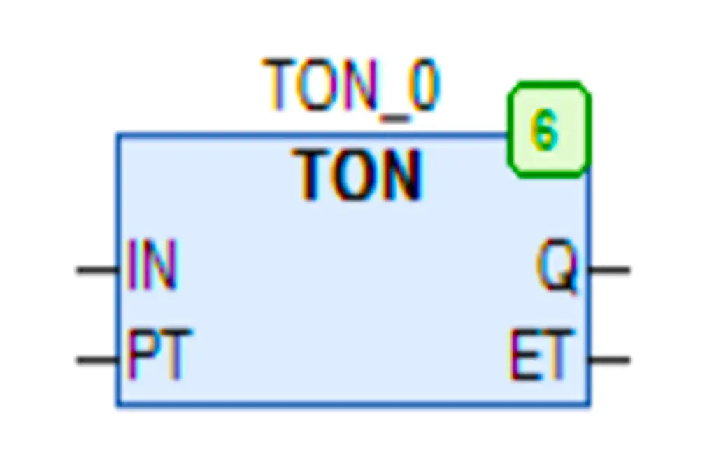
As long as the input condition is true, the timer will work. If the input is true and the set time elapses, then the output remains true as long as the input is true.

TOF (Timer Off)

The Timer-Off type is an off-delay timer. It means that when the input is received, the output turns on. When the input goes off, then the timer starts and after the set time elapses, the output goes off.

TOF Timer in CodeSys

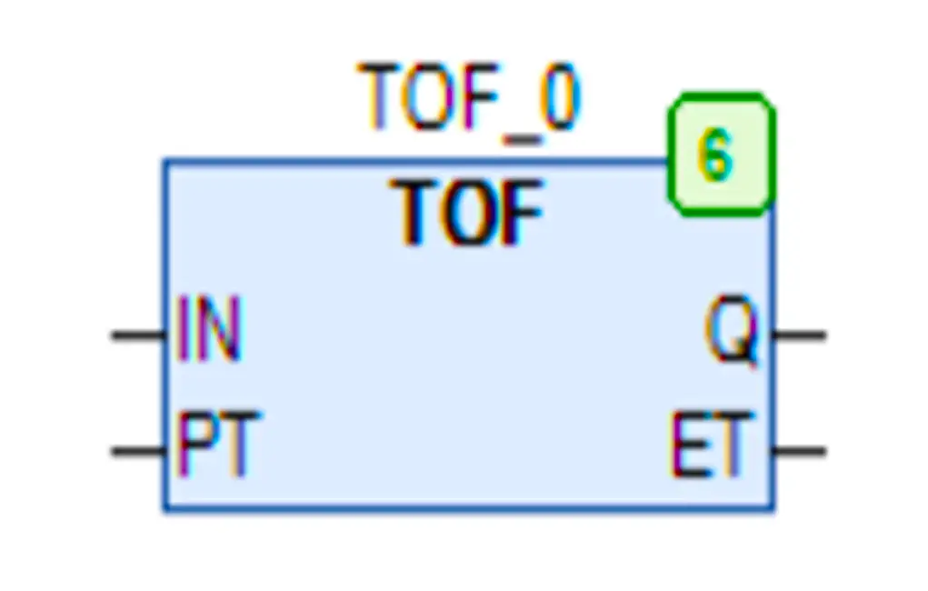
In between if the input goes true, then the timer’s current value too becomes zero and the output remains on. As long as the input condition is false after the true condition, the timer will work. If the input is false and the set time elapses, then the output goes false.

TP (Pulse Timer)

The TP timer type is a pulse delay timer. It means that when the input is received as a positive pulse or negative pulse, the output turns on for the set time. After the set time elapses, then the output goes false.

TP Timer in CodeSys

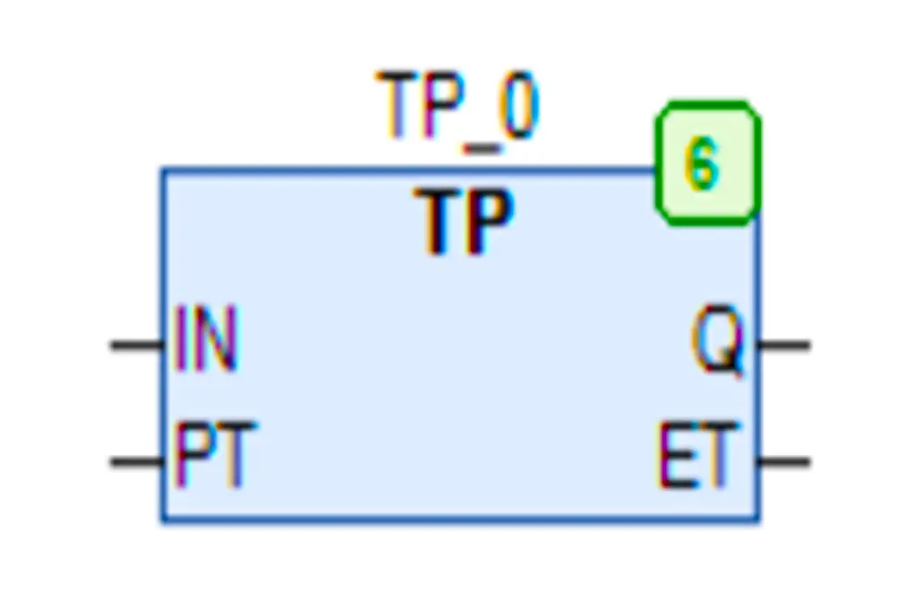
In between, whatever be the condition of the input, the timer will remain on till the set timer elapses and during that time, the output too will remain on. That means it is a latch-type instruction.

If you liked this article, then please subscribe to our YouTube Channel for Instrumentation, Electrical, PLC, and SCADA video tutorials.

You can also follow us on Facebook and Twitter to receive daily updates.

Read Next:

  • Algorithms in PLC Programming
  • Industrial Automation Mobile App
  • Principle of Single-Phase Preventer Relay
  • Omron PLC Programming Course in HINDI
  • Which Language is Best for PLC Programming?
Don't Miss Our Updates
Be the first to get exclusive content straight to your email.
We promise not to spam you. You can unsubscribe at any time.
Invalid email address
You've successfully subscribed !
Software Troubleshooting Errors and Faults in Siemens PLC
How to Export Data from WinCC Runtime Advanced into Excel using VB Script
Explaining Various Types of Analog Instruments
Create Ladder Diagram from Boolean Logic
Difference between DCS, PLC, and RTU ?
Share This Article
Facebook Whatsapp Whatsapp LinkedIn Copy Link
Share
Leave a Comment

Leave a Reply Cancel reply

Your email address will not be published. Required fields are marked *

Stay Connected

128.3kFollowersLike
69.1kFollowersFollow
208kSubscribersSubscribe
38kFollowersFollow

Categories

Recent Comments

  • Guifty Shimica on Top Non-PLC Certification Courses for Automation Professionals
  • Guifty Shimica on Top Non-PLC Certification Courses for Automation Professionals
  • MIHARITSOA Aina Sitraka on Top Non-PLC Certification Courses for Automation Professionals
  • Vaishnavi on Free Instrumentation Course for Trainee Engineers

Related Articles

Scan cycle of a Siemens PLC

OB1 – Main Cyclic Organization Block in TIA Portal

PLC Scan Time

PLC Scan Time

Automated Garage Gate Control - PLC Ladder Logic

Automated Garage Gate Control – PLC Ladder Logic

Siemens Industrial Laptop (Simatic Field PG)

Connect to the Siemens S7 PLC

Programmable Logic Controller (PLC) PLC Maintenance Check Points

Programmable Logic Controller Maintenance Check Points

Types of Digital Outputs in PLC

Types of Digital Outputs in PLC

Most Asked Questions on SCADA

Most Asked Questions on SCADA with Answers

User Defined Data Types - UDT

User Defined Data Types (UDT) – Purpose, Need, Tutorial

More Articles

Magnatic Level Indicators Working Animation

Magnetic Level Indicators Working Animation

Coriolis Mass Flowmeter Principle

Coriolis Mass Flow Meter Working Principle

What is Oscilloscope

What is Cathode Ray oscilloscope ?

PLC engineering software

How to Download GX Works? Mitsubishi PLC Software

Ultrasonic Doppler Flow Meter Advantages and Disadvantages

Ultrasonic Doppler Flow Meter Advantages and Disadvantages

Pictorial Fluid Power Diagram

Hydraulic and Pneumatic P&ID Diagrams and Schematics

Power Electronics Objective Questions

PWM based Inverters in Power Electronics Quiz

Root Cause Analysis of Differential Pressure Level Transmitter

Root Cause Analysis of Differential Pressure Level Transmitter

Follow US
All rights reserved. Reproduction in whole or in part without written permission is prohibited.
Welcome Back!

Sign in to your account

Username or Email Address
Password

Lost your password?