Inst ToolsInst ToolsInst Tools
  • Courses
  • Automation
    • PLC
    • Control System
    • Safety System
    • Communication
    • Fire & Gas System
  • Instrumentation
    • Design
    • Pressure
    • Temperature
    • Flow
    • Level
    • Vibration
    • Analyzer
    • Control Valve
    • Switch
    • Calibration
    • Erection & Commissioning
  • Interview
    • Instrumentation
    • Electrical
    • Electronics
    • Practical
  • Q&A
    • Instrumentation
    • Control System
    • Electrical
    • Electronics
    • Analog Electronics
    • Digital Electronics
    • Power Electronics
    • Microprocessor
  • Request
Search
  • Books
  • Software
  • Projects
  • Process
  • Tools
  • Basics
  • Formula
  • Power Plant
  • Root Cause Analysis
  • Electrical Basics
  • Animation
  • Standards
  • 4-20 mA Course
  • Siemens PLC Course
Reading: Radiation Pyrometer Working Principle
Share
Notification Show More
Font ResizerAa
Inst ToolsInst Tools
Font ResizerAa
  • Courses
  • Design
  • PLC
  • Interview
  • Control System
Search
  • Courses
  • Automation
    • PLC
    • Control System
    • Safety System
    • Communication
    • Fire & Gas System
  • Instrumentation
    • Design
    • Pressure
    • Temperature
    • Flow
    • Level
    • Vibration
    • Analyzer
    • Control Valve
    • Switch
    • Calibration
    • Erection & Commissioning
  • Interview
    • Instrumentation
    • Electrical
    • Electronics
    • Practical
  • Q&A
    • Instrumentation
    • Control System
    • Electrical
    • Electronics
    • Analog Electronics
    • Digital Electronics
    • Power Electronics
    • Microprocessor
  • Request
Follow US
All rights reserved. Reproduction in whole or in part without written permission is prohibited.
Inst Tools > Blog > Temperature Measurement > Radiation Pyrometer Working Principle

Radiation Pyrometer Working Principle

Last updated: September 22, 2018 7:51 pm
Editorial Staff
Temperature Measurement
1 Comment
Share
4 Min Read
SHARE

As discussed earlier, an Optical Pyrometer can be not only be used for temperature measurement, but also can be used to see the heat that is measured. The observer is actually able to calculate the infrared wavelength of the heat produced and also see the heat patterns by the object. But the amount of heat that the device can sense is limited to 0.65 microns. This is why the radiation pyrometer is more useful, as it can be used to measure all temperatures of wavelengths between 0.70 microns and 20 microns.

Radiation Pyrometer

The wavelengths measured by the device are known to be pure radiation wavelengths, that is, the common range for radioactive heat. This device is used in places where physical contact temperature sensors like Thermocouple, RTD, and Thermistors would fail because of the high temperature of the source.

The main theory behind a radiation pyrometer is that the temperature is measured through the naturally emitted heat radiation by the body. This heat is known to be a function of its temperature. According to the application of the device, the way in which the heat is measured can be summarized into two:

  1. Total Radiation Pyrometer – In this method, the total heat emitted from the hot source is measured at all wavelengths.
  2. Selective Radiation Pyrometer – In this method, the heat radiated from the hot source is measured at a given wavelength.

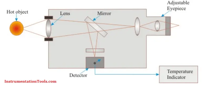
As shown in the figure below, the radiation pyrometer has an optical system, including a lens, a mirror and an adjustable eye piece. The heat energy emitted from the hot body is passed on to the optical lens, which collects it and is focused on to the detector with the help of the mirror and eye piece arrangement. The detector may either be a thermistor or photomultiplier tubes. Though the latter is known for faster detection of fast moving objects, the former may be used for small scale applications. Thus, the heat energy is converted to its corresponding electrical signal by the detector and is sent to the output temperature display device.

Radiation Pyrometer Working Principle

Advantages

  • The device can be used to measure very high temperatures without direct contact with the hot source (Molten metal).
  • The biggest advantage is that the optical lens can be adjusted to measure temperature of objects that are even 1/15 inch in diameter and that too kept at a long s=distance from the measuring device.
  • The sight path of the device is maintained by the construction of the instrument components, such as the lens and curved mirrors.

Limitations

  • Availability of optical materials limit on the wavelengths that can be measured.
  • The surface of the hot object should be clean. It should not be oxidized. Scale formation does not allow to measure radiation accurately.
  • Emissivity correction is required. Change in emissivity with temperature need to be considered.

Also Read: Temperature Sensors Interview Questions

Don't Miss Our Updates
Be the first to get exclusive content straight to your email.
We promise not to spam you. You can unsubscribe at any time.
Invalid email address
You've successfully subscribed !

Continue Reading

Distributed Temperature Sensors (DTS) in Power Lines
Why RTD installed after the Orifice Plate ?
Important Factors for Thermocouple Selection
Temperature Switch Working Principle
Basics of Temperature Switch
Pressure and Temperature Gauges
Share This Article
Facebook Whatsapp Whatsapp LinkedIn Copy Link
Share
1 Comment
  • Satyawan says:
    June 30, 2021 at 1:24 am

    I need instrument notes

    Reply

Leave a Reply Cancel reply

Your email address will not be published. Required fields are marked *

Stay Connected

128.3kFollowersLike
69.1kFollowersFollow
210kSubscribersSubscribe
38kFollowersFollow

Categories

Explore More

Thermowell Wake Frequency Calculation
Disadvantages of Resistance Temperature Detectors
Free Download Thermocouple Calculator
What is a Thermopile ?
Thermowell Installation near Critical Equipment
Temperature Transmitter Preventive Maintenance
Optical Pyrometer Working Principle
Pneumatic Temperature Transmitter with Sensor Principle

Keep Learning

Electrical Resistance Temperature Curves of RTD

Resistance Temperature Detectors (RTD) Construction

field-mounted thermocouple

Thermocouple Extension Wires

RTD lead resistances Wiring

Resistance Temperature Detectors Working Principle

RTD Accuracy

What is RTD Accuracy ?

Seebeck Effect

Seebeck Effect Theory

RTD Calculator : Calculate Temperature from Resistance

RTD Calculator : Calculate Temperature from Resistance

Temperature Gauges and Elements Specifications

Temperature Gauges and Elements : Detailed Specifications

Filled-bulb Temperature Measurement

Filled-bulb Temperature Sensors

Learn More

plc-analog-input-card-conversion-formula

PLC Analog Input Conversion Formula

Tree (chicken foot) topology

Fieldbus Device Capability

Combining Independent Voltage Sources in Series

Combining Independent Voltage Sources in Series

PID Loop Tuning

PID Controller Loop Tuning Questions and Answers – Part 1

Contextual HMI

What is Contextual HMI? – HMI Screens on a Mobile or Tablet

PLC Control for Baking Machines Logic

PLC Programming for Baking with Auto and Manual Modes

Smoke Detector Testing Procedure

Smoke Detector Testing Procedure

What are Pressure Sensing Lines

What are Pressure Sensing Lines? – Causes of Errors in Measurement

Menu

  • About
  • Privacy Policy
  • Copyright

Quick Links

  • Learn PLC
  • Helping Hand
  • Part Time Job

YouTube Subscribe

Follow US
All rights reserved. Reproduction in whole or in part without written permission is prohibited.
Welcome Back!

Sign in to your account

Username or Email Address
Password

Lost your password?