Inst ToolsInst ToolsInst Tools
  • Courses
  • Automation
    • PLC
    • Control System
    • Safety System
    • Communication
    • Fire & Gas System
  • Instrumentation
    • Design
    • Pressure
    • Temperature
    • Flow
    • Level
    • Vibration
    • Analyzer
    • Control Valve
    • Switch
    • Calibration
    • Erection & Commissioning
  • Interview
    • Instrumentation
    • Electrical
    • Electronics
    • Practical
  • Q&A
    • Instrumentation
    • Control System
    • Electrical
    • Electronics
    • Analog Electronics
    • Digital Electronics
    • Power Electronics
    • Microprocessor
  • Request
Search
  • Books
  • Software
  • Projects
  • Process
  • Tools
  • Basics
  • Formula
  • Power Plant
  • Root Cause Analysis
  • Electrical Basics
  • Animation
  • Standards
  • 4-20 mA Course
  • Siemens PLC Course
Reading: How to Test TRIAC with Multimeter
Share
Font ResizerAa
Inst ToolsInst Tools
Font ResizerAa
  • Courses
  • Design
  • PLC
  • Interview
  • Control System
Search
  • Courses
  • Automation
    • PLC
    • Control System
    • Safety System
    • Communication
    • Fire & Gas System
  • Instrumentation
    • Design
    • Pressure
    • Temperature
    • Flow
    • Level
    • Vibration
    • Analyzer
    • Control Valve
    • Switch
    • Calibration
    • Erection & Commissioning
  • Interview
    • Instrumentation
    • Electrical
    • Electronics
    • Practical
  • Q&A
    • Instrumentation
    • Control System
    • Electrical
    • Electronics
    • Analog Electronics
    • Digital Electronics
    • Power Electronics
    • Microprocessor
  • Request
Follow US
All rights reserved. Reproduction in whole or in part without written permission is prohibited.
Inst Tools > Blog > Power Electronics > How to Test TRIAC with Multimeter

How to Test TRIAC with Multimeter

Last updated: September 19, 2016 4:10 am
Editorial Staff
Power Electronics
7 Comments
Share
2 Min Read
SHARE

How to test TRIAC with Digital Multimeter OR using Ohmmeter?

In this short post we will discuss about how to test the Triac.

triac

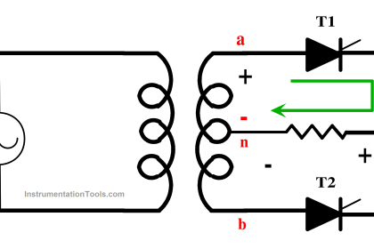
Introduction about Triac:

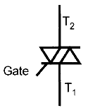
  1. TRIAC = TRIode for Alternating Current.
  2. The TRIAC is 5 layer, 3 terminal Power semiconductor device.
  3. It has a pair of phase controlled SCRs connected in inverse parallel manner on the same chip.
  4. It is a bidirectional device, means it can conduct current in both the directions.

Procedure to test the TRIAC


Step by step Procedure to test the triac:

  1. Keep the digital multimeter into Ohmmeter mode.
  2. Using a junction diode determine which ohmmeter lead is positive and which is negative. The ohmmeter will indicate continuity only when the positive lead is connected to the anode and the negative lead is connected to the cathode.
  3. Connect the positive lead of Ohmmeter to MT2 and the negative lead to MT1. The ohmmeter should indicate no continuity through the triac.
  4. Using a jumper lead connect the Gate of the Triac to MT2. The multimeter should indicate a forward diode junction.
  5. Reconnect the Triac so that MT1 is connected to the positive lead of ohmmeter and MT2 is connected to the negative lead. The multimeter should indicate no continuity through a Triac.
  6. Using a jumper lead, again connect the gate to MT2. The ohmmeter should indicate a forward diode junction.
Don't Miss Our Updates
Be the first to get exclusive content straight to your email.
We promise not to spam you. You can unsubscribe at any time.
Invalid email address
You've successfully subscribed !

Continue Reading

Turning Off SCR – Commutation
What is Power Electronics? Evolution, Block Diagram, Advantages
Thyristor Commutation Techniques – Types, Working Principles
Power Electronic Devices Specification and Classification
MCT (MOS Controlled Thyristor) – Symbol, Working, Characteristics, Advantages
Introduction to Thyristor – History, Types, Principle, Advantages
Share This Article
Facebook Whatsapp Whatsapp LinkedIn Copy Link
Share
7 Comments
  • Jesse says:
    March 9, 2020 at 10:26 pm

    I am currently testing a triac, I’m getting readings in megaohms across M1 and M2 , is that close enough to no reading or open?

    Reply
    • Andres says:
      June 30, 2021 at 3:55 am

      I am getting readings around 50 ohm with floating gate pin. Mine obviously is damaged.
      You should test it with the diode option not the ohms.

      Reply
      • Joe says:
        August 11, 2021 at 8:03 am

        hai andres.. What is the actual reading (ohm) for the triac after test. If still inbgood condition. Tq

        Reply
  • Himynameis says:
    October 11, 2022 at 1:10 am

    I observed that one of the pins should conduct with the tab. If none conducts, you have a broken triac.

    Reply
  • André Giguère says:
    April 15, 2023 at 4:49 am

    Very interesting article on how to test a TRIAC

    Reply
  • S. X. says:
    September 19, 2023 at 4:51 am

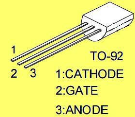
    I have some new Triacs. Pin1, 2, 3 are A1,A2,G.
    50 Ohm is between A1 and G.

    Reply
  • jose protacio says:
    May 9, 2024 at 8:02 am

    hi S.X.
    mine reads about 60 ohms forward and reverse A1 to G and its good

    Reply

Leave a Reply Cancel reply

Your email address will not be published. Required fields are marked *

Stay Connected

128.3kFollowersLike
69.1kFollowersFollow
210kSubscribersSubscribe
38kFollowersFollow

Categories

Explore More

Phase Controlled Rectifier – Half Controlled Rectifier with R Load
Crowbar fault protection circuit
Power Electronics Objective Questions
R R-C Firing Circuits Disadvantages
Types of IGBT
Top 100 Power Electronics Projects for Engineering Students
Power Transistor – Structure, Biasing, Characteristics, Advantages
Power Diode – Characteristics, Construction, Working, Advantages

Keep Learning

Phase Controlled Half Wave Rectifier RL Load

Power Electronics – Phase Controlled Half Wave Rectifier RL Load

RC Triggering

SCR Triggering Methods

Basics of Thyristor

Basics of Thyristor

Full-Controlled Rectifier Working Principle

Single-Phase Mid-Point Converter – Bridge Rectifier with Center Tap

Power MOSFET Symbols

Power MOSFET – Symbol, Types, Working, Characteristics, Advantages

How to test SCR using Multimeter

How to test SCR using Multimeter

Thyristor Interview Questions & Answers

Thyristor Interview Questions & Answers

Resistance firing of an SCR in a half-wave circuit

Thyristor Triggering Circuits – Types, Explanation, Waveforms (SCR)

Learn More

pn-junction-energy-diagrams

Energy Diagrams of PN Junction & Depletion Region

PLC Motor Control Circuit

Motor Trip Logic using PLC Programming

Ziegler-Nichols Open Loop Tuning Procedure

Ziegler-Nichols Open Loop Tuning Procedure

How do AC drives work

How do AC Drives Work? – Variable Frequency Drive (VFD)

Problem in Water Level Control System

Problem in Water Level Control System

PLC based Automatic Bell System

PLC based Automatic Bell System for a School

Argonite Fire Suppression System Animation

Argonite Fire Suppression System Working Principle

Questions on Level Switches

Questions on Level Switches

Menu

  • About
  • Privacy Policy
  • Copyright

Quick Links

  • Learn PLC
  • Helping Hand
  • Part Time Job

YouTube Subscribe

Follow US
All rights reserved. Reproduction in whole or in part without written permission is prohibited.
Welcome Back!

Sign in to your account

Username or Email Address
Password

Lost your password?