Motors are a common type of output used in industrial automation. Motors control and interlocking must be properly done by a programmer for efficient and reliable operation. When he is writing the logic, he often thinks first which language to write in.
One of the most highly popular languages in PLC programming is structured text. Due to it’s syntax similar to an IT language program, it is preferred for complex calculations and logic writing. In this post, we will see how to interlock two motors and run them simultaneously through structured text PLC programming.
Motor Interlocking and Control
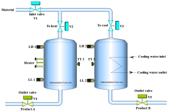
Let us understand the case scenario first. There are two motors in the circuit. When the start button is pressed, the first motor will run for 10 seconds and after that, it will stop and the second motor will run for 10 seconds. This continues until the stop button is pressed, which resets and stops the whole logic. Now, when the first motor is running and someone presses the bypass button, then it will stop immediately and start the second motor. The same goes for the second motor.
Now, let us start the logic development. First, let us freeze the IOs.
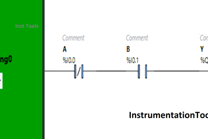
There are four digital inputs – start push button, stop push button, motor-1 bypass button, and motor-2 bypass button.
There are two digital outputs – motor-1 and motor-2.
Structured Text PLC Example
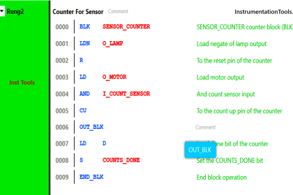
Refer to the below image. As per the first condition, when the start button is pressed, then logic starts. So, we write it in an if statement and set the logic running bit to 1.
Now, when the stop button is pressed, then logic stops. So, we write it in an if statement and set the logic running bit to 0.
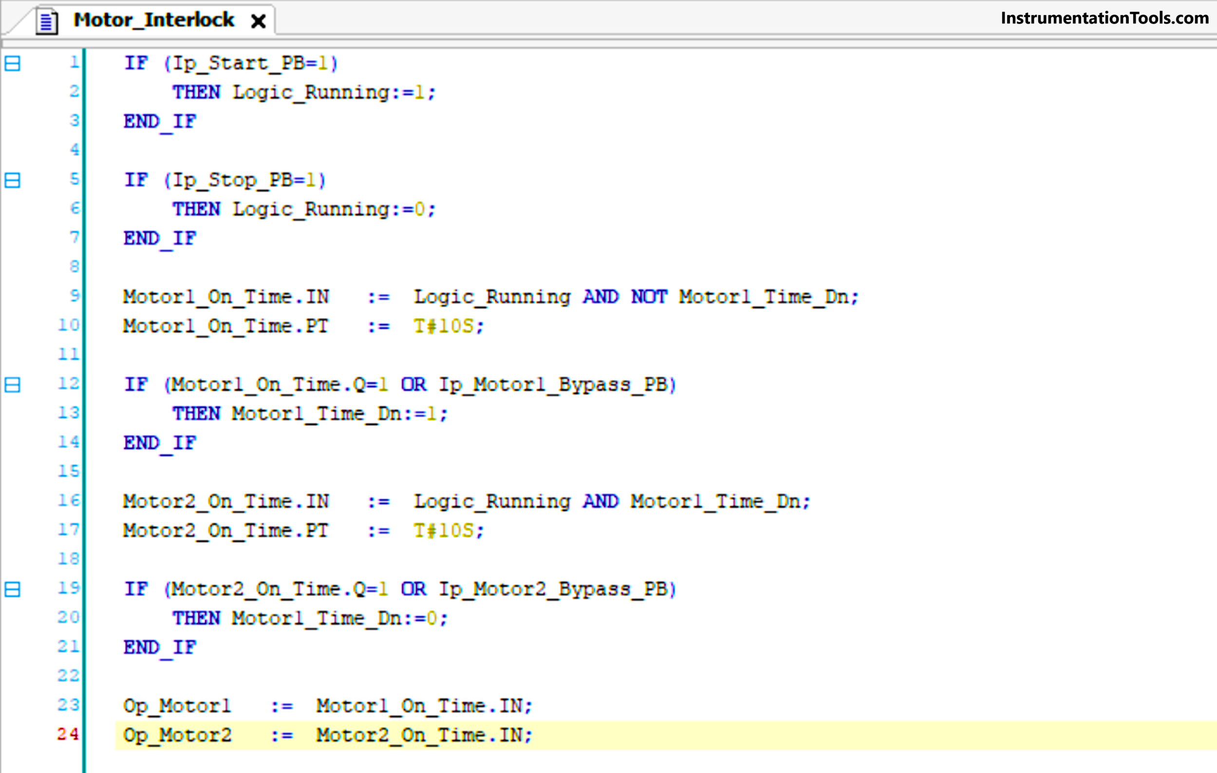
Now, we start the timer logic. When logic starts, then motor-1 runs for 10 seconds and then stops. So, we link the logic running bit and an internal bit – motor-1 timer done bit as negate. When the timer finishes, then we set motor-1 timer done bit to 1 and this cuts off the timer-1.
Next, motor-2 runs for 10 seconds after motor-1 timer has been done and then stops. So, we link the logic running bit and the internal bit – motor-1 timer done bit. When the timer finishes, then we set motor-1 timer done bit to 0 and this cuts off the timer-2. The cycle repeats once again.
To bypass the timers, we have used two separate push buttons. On pressing the motor-1 bypass button, timer-1 will be done immediately. So, we link it with the OR condition with the motor-1 timer done. On pressing the motor-2 bypass button, timer-2 will be done immediately. So, we link it with the OR condition with the motor-2 timer done.
Now, to turn the motors on or off, we link the timer input condition to it. This makes the logic simple to use.
In this way, we saw how to operate the motors simultaneously with interlocks.
Read Next:
- PLC Ladder Logic for Alarm Security System
- How Modbus is used in Industrial Networks?
- Conveyor Speed Logic using Structured Text
- FBD PLC Example for Traffic Light System
- Burglar Alarm Security System PLC FBD Logic


thanks for great subject and good explanation