By using this site, you agree to the Privacy Policy and Terms of Use.
Accept
Inst ToolsInst ToolsInst Tools
  • Ask
  • Courses
  • Videos
  • Q & A
    • Interview
      • Instrumentation
      • Electronics
      • Electrical
      • Practical Questions
    • MCQ
      • Instrumentation MCQ
      • Electrical MCQ
      • Electronics MCQ
      • Control Systems MCQ
      • Analog Electronics MCQ
      • Digital Electronics MCQ
      • Power Electronics MCQ
      • Microprocessor MCQ
      • Multiple Choice Questions
  • EE
    • Electronics
      • Electronics Q & A
      • Electronic Basics
      • Electronic Devices & Circuits
      • Electronics Animation
      • Digital Electronics
    • Electrical
      • Electrical Basics
      • Electrical Q & A
      • Power Electronics
      • Electrical Machines
      • Electrical Animation
      • Power Systems
      • Switchgear & Protection
      • Transmission & Distribution
  • Measure
    • Control Valves
    • Calibration
    • Temperature
    • Pressure
    • Flow
    • Level
    • Analyzers
    • Switches
    • Vibration
    • Solenoid Valve
  • Control
    • PLC Tutorials
    • Control Systems
    • Safety Instrumented System (SIS)
    • Communication
    • Fire & Gas System
  • More
    • Design
    • Tools
    • Animation
    • Basics
    • Formulas
    • Standards
    • TextBooks
    • Common
    • Software
    • Excel Tools
    • Erection & Commissioning
    • Process Fundamentals
    • Videos
    • Books
Search
All rights reserved. Reproduction in whole or in part without written permission is prohibited.
Reading: STL Programming – SET, RESET, ASSIGN
Share
Notification Show More
Font ResizerAa
Inst ToolsInst Tools
Font ResizerAa
  • Ask
  • Courses
  • Videos
  • Q & A
  • EE
  • Measure
  • Control
  • More
Search
  • Ask
  • Courses
  • Videos
  • Q & A
    • Interview
    • MCQ
  • EE
    • Electronics
    • Electrical
  • Measure
    • Control Valves
    • Calibration
    • Temperature
    • Pressure
    • Flow
    • Level
    • Analyzers
    • Switches
    • Vibration
    • Solenoid Valve
  • Control
    • PLC Tutorials
    • Control Systems
    • Safety Instrumented System (SIS)
    • Communication
    • Fire & Gas System
  • More
    • Design
    • Tools
    • Animation
    • Basics
    • Formulas
    • Standards
    • TextBooks
    • Common
    • Software
    • Excel Tools
    • Erection & Commissioning
    • Process Fundamentals
    • Videos
    • Books
Follow US
All rights reserved. Reproduction in whole or in part without written permission is prohibited.
Inst Tools > Blog > PLC Tutorials > STL Programming – SET, RESET, ASSIGN

STL Programming – SET, RESET, ASSIGN

We are going to explain how to use SET, RESET and ASSIGN instructions with STL programming in a PLC.

Last updated: September 28, 2022 2:23 pm
Hussien Ghareb
PLC Tutorials
No Comments
Share
6 Min Read
SHARE

Hello and welcome to another lesson that is a part of articles series that discuss the Statement List language, that is the second article in this series, and today we are going to explain how to use SET, RESET and ASSIGN instructions with STL language and we will ensure that you have got the idea by giving a related example.

Contents
Initiate a Bit with STL LanguageAssign Instruction (=)SET InstructionRESET InstructionExample for SET & RESET InstructionsSummary

So let us start and if you did not attend the first lesson, please check it at first Here.

Initiate a Bit with STL Language

As we discussed in the previous lesson STL is very unique and concise language. Tt has totally different in the interfacing construction from the LAD language.

The logic of the STL language applies across a very important bit that is called RLO (Result of Logic Operation). This bit is responsible for scanning the status of the code Lines and passes that logic to the process outputs.

So here we are getting into how to make these instructions, at first you have to know that there are two ways to initiate a memory bit in the code logic, they are just slightly different but in general, they can handle the same function.

Note: We are discussing these programming using Siemens Tia Portal.

Assign Instruction (=)

Format

= < Bit >   // used for a BOOL data type (I, Q, M, L, D)

Description

= <Bit> writes the RLO into the addressed bit for a switched-on master control relay if MCR = 1. If MCR = 0, then the value 0 is written to the addressed bit instead of RLO.

So if the conditions status (RLO) is true the assigned bit will be true, but if any of those conditions will be not true the assigned bit will be in the false state.

Example

For the next Fig you can see that all of the input conditions (RLO) are achieved so the output Q0.0 is turned to be in the True state.
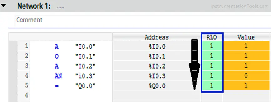
Input conditions - RLO

Unlike what we can see here in Line No. (4) the value of I0.3 becomes 1 and this value is NOT ANDED with the previous values.

So the RLO becomes false at this line and by its role the assigned output Q0.0 also becomes false.
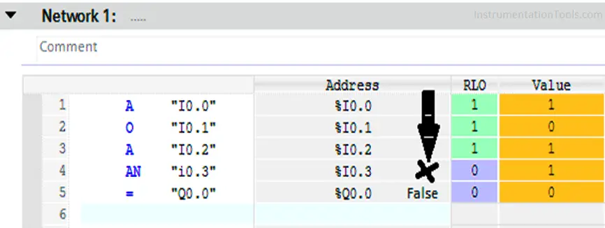
Result of Logic Operation

SET Instruction

Format

S < Bit > // the data type is Bool

Description

S (set bit) places a “1” in the addressed bit if RLO = 1 and the switched-on master control relay MCR = 1.

But If RLO = 0, then the addressed bit does not change and it will remain True.

RESET Instruction

Format

R < Bit > // the data type is Bool

Description

R (reset bit) places a “0” in the addressed bit if RLO = 1 and master control relay MCR = 1.

But If RLO = 0, then the addressed bit will not be changed and it will remain in the false state.

Example for SET & RESET Instructions

Here you can see that all the conditions are achieved and the output Q0.0 is launched. (Left side image)

And after that when the RLO returns to be Zero, the output bit Q0.0 retains its value till the Reset instruction is launched. (Right side image)

SET & RESET Instructions using STL Programming

Here we are launching the Reset instruction by turn I0.0 ON to make Q0.0 false again.

Notice that also however I0.0 returns to Zero the output Q0.0 would retain its value (False).

STL RESET Program

Right-side image -> when reset bit is activated. Left-side image -> after the reset.

Summary

So, as we said before we can use both methods to handle the same function but with the Assign method you do not need a Reset function as the assigned bit would return to Zero once just one of the conditions is not achieved, unlike the SET & RESET method if the conditions are achieved, the output bit will be launched and it will not return to zero till the Reset instruction is activated, Even the conditions return to Zero the output bit Q0.0 will retain its value (1) till you reset the bit.

If you liked this article, then please subscribe to our YouTube Channel for PLC and SCADA video tutorials.

You can also follow us on Facebook and Twitter to receive daily updates.

Read Next:
  • FB and FC Programming in PLC
  • Edge Detection in PLC Programming
  • Statement List (STL) to Find Highest Value
  • Always ON and OFF Bit using Ladder Logic and Statement List
  • Hardware Description Language Objective Questions
Don't Miss Our Updates
Be the first to get exclusive content straight to your email.
We promise not to spam you. You can unsubscribe at any time.
Invalid email address
You've successfully subscribed !
Download Allen Bradley RSLogix PLC Software
What is SCADA ? How does SCADA Works ?
What is Process Control?
PLC Programming Course Online Free
FC Function in Siemens PLC
Share This Article
Facebook Whatsapp Whatsapp LinkedIn Copy Link
Share
Leave a Comment

Leave a Reply Cancel reply

Your email address will not be published. Required fields are marked *

Stay Connected

128.3kFollowersLike
69.1kFollowersFollow
208kSubscribersSubscribe
38kFollowersFollow

Recent Comments

  • MIHARITSOA Aina Sitraka on Top Non-PLC Certification Courses for Automation Professionals
  • Vaishnavi on Free Instrumentation Course for Trainee Engineers
  • anuj kapoor on DCS Program to Maintain Draft in Furnace
  • anuj kapoor on IoT based Smart Boiler Control System with Cloud PLC and SCADA

Related Articles

Counter Count Down Bit

Down Counter PLC Program

Structured Text Automatic Gate Logic

Structured Text PLC Programming for Automatic Gate Control

Advanced PLC Programming Training Course

Advanced PLC Course with Programming and Simulation

DCS Commissioning Steps

DCS Commissioning Steps

PLC Fault Diagnosis - PLC Training Documents

PLC Fault Diagnosis – PLC Training Documents

Ladder Logic Vs. Other Programming Languages - PLC Basics

Ladder Logic Vs. Other Programming Languages – PLC Basics

PLC Automatic Control of Two Outputs with one Input

PLC Automatic Control of Two Outputs with one Input

Difference Between PLC and CNC Machine

Difference Between PLC and CNC Machine

More Articles

Equal Flow Balance Operation of Parallel Compressors

Types of Surge Control for Parallel Gas Compressors

PLC Code to Start & Stop Motor and Pump as per Logic

PLC Code to Start & Stop Motor and Pump as per Logic

Semiconductors Diodes Questions & Answers

Semiconductors Diodes Questions & Answers

Electric Circuits Objective Questions

Electric Circuits Objective Questions – Set 12

Importance of Neutral Wire

Importance of Neutral Wire

What is a Floating License - Automation Software Systems

What is a Floating License? – Automation Software Systems

What is Chemical Vapor Deposition

What is Chemical Vapor Deposition? – The Ultimate Guide

Discrete Manufacturing Automation

Discrete Manufacturing Automation

Follow US
All rights reserved. Reproduction in whole or in part without written permission is prohibited.
Welcome Back!

Sign in to your account

Username or Email Address
Password

Lost your password?