Inst ToolsInst ToolsInst Tools
  • Courses
  • Automation
    • PLC
    • Control System
    • Safety System
    • Communication
    • Fire & Gas System
  • Instrumentation
    • Design
    • Pressure
    • Temperature
    • Flow
    • Level
    • Vibration
    • Analyzer
    • Control Valve
    • Switch
    • Calibration
    • Erection & Commissioning
  • Interview
    • Instrumentation
    • Electrical
    • Electronics
    • Practical
  • Q&A
    • Instrumentation
    • Control System
    • Electrical
    • Electronics
    • Analog Electronics
    • Digital Electronics
    • Power Electronics
    • Microprocessor
  • Request
Search
  • Books
  • Software
  • Projects
  • Process
  • Tools
  • Basics
  • Formula
  • Power Plant
  • Root Cause Analysis
  • Electrical Basics
  • Animation
  • Standards
  • 4-20 mA Course
  • Siemens PLC Course
Reading: Start Stop of one Motor from the same Push button PLC program
Share
Font ResizerAa
Inst ToolsInst Tools
Font ResizerAa
  • Courses
  • Design
  • PLC
  • Interview
  • Control System
Search
  • Courses
  • Automation
    • PLC
    • Control System
    • Safety System
    • Communication
    • Fire & Gas System
  • Instrumentation
    • Design
    • Pressure
    • Temperature
    • Flow
    • Level
    • Vibration
    • Analyzer
    • Control Valve
    • Switch
    • Calibration
    • Erection & Commissioning
  • Interview
    • Instrumentation
    • Electrical
    • Electronics
    • Practical
  • Q&A
    • Instrumentation
    • Control System
    • Electrical
    • Electronics
    • Analog Electronics
    • Digital Electronics
    • Power Electronics
    • Microprocessor
  • Request
Follow US
All rights reserved. Reproduction in whole or in part without written permission is prohibited.
Inst Tools > Blog > PLC Tutorials > Start Stop of one Motor from the same Push button PLC program

Start Stop of one Motor from the same Push button PLC program

Last updated: March 4, 2021 11:32 am
Editorial Staff
PLC Tutorials
4 Comments
Share
2 Min Read
SHARE

In some applications, it may be required to use one single push button in order to save inputs or for whatever reason to start and stop the same motor.

Contents
Start Stop of one Motor from same Push buttonPLC Program

It is simple, all you need is to acquire an instruction that could register the output status (on or off), and upon the status of the output, it should decide the next action to on or off the output.

Note: The best practice to learn the PLC programming is to start writing the PLC program, take your time before you review the answer.

Download: Tia Portal

Inputs & Outputs:

I0.0: Push-button

Q0.0: Motor

M0.0: Positive Trigger

M0.1: Negative Trigger

Start Stop of one Motor from same Push button

Start Stop of one Motor from same Push button PLC program

PLC Program

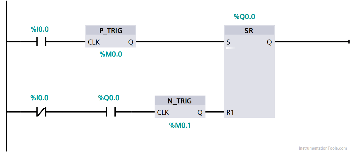
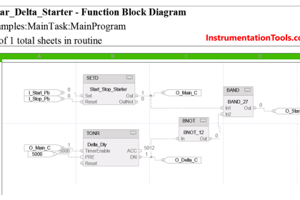
In this network you can find the SR flip flop where:

If the motor Q0.0 is OFF and the Push-button (PB) I0.0 is pressed for one time, the set value would be energized and sets the output Q0.0 to ON. So the motor will be started.

If the motor Q0.0 is ON and the PB I0.0 is pressed for one time, the reset value would be energized and sets the output Q0.0 to OFF. So the motor will be stopped.

The positive edge detector in the set branch is used to ensure that the press of the I0.0 should be executed for a single scan cycle.

The negative edge detector is to ensure that the reset should not be energized unless the motor is ON.

Author: Karim Ali Anwar

If you liked this article, then please subscribe to our YouTube Channel for PLC and SCADA video tutorials.

You can also follow us on Facebook and Twitter to receive daily updates.

Read Next:

  • PLC Logic Stair-Case wiring
  • InTouch Scada Trends
  • PLC Move Instruction
  • Latching Function of PLC
  • Siemens S7-1200 Simulator
Don't Miss Our Updates
Be the first to get exclusive content straight to your email.
We promise not to spam you. You can unsubscribe at any time.
Invalid email address
You've successfully subscribed !

Continue Reading

PLC Programming Example on Timers Function Block
Parts of PLC
#18 PLC Best Practices – Store PLC Hard Stop Events from Faults
Gas Turbine Temperature Alarms using Siemens TIA Portal
Retentive ON Delay Timer using PLC
What is Namur Digital Input Card?
Share This Article
Facebook Whatsapp Whatsapp LinkedIn Copy Link
Share
4 Comments
  • sai says:
    January 5, 2021 at 12:01 pm

    thank u inst tools. with this blog i learn so many new concepts which are help to reach the real time industrial basis

    Reply
  • Archimedes says:
    March 10, 2021 at 12:34 pm

    thank you sir for this site!
    All these tutorials are very useful for plc programming. I wish to be able to save them to our PC…

    Reply
  • Sohel khalfa says:
    September 14, 2021 at 8:11 am

    Start stop puss botton se vfd se motor kese opret kare

    Reply
  • hamdan firas says:
    March 8, 2022 at 3:49 pm

    good ,but u forgot nc coil before pos edge detector that ensure q0.0 is off

    Reply

Leave a Reply Cancel reply

Your email address will not be published. Required fields are marked *

Stay Connected

128.3kFollowersLike
69.1kFollowersFollow
210kSubscribersSubscribe
38kFollowersFollow

Categories

Explore More

FactoryTalk Studio and SQL Server for Data Logging
Basics of PLC Programming
What is an RTU? – Remote Terminal Unit
How to Download EcoStruxure Machine Expert? Schneider PLC Software
Finding the Best PLC for Your Project – Tips and Tricks
Introduction to PLC – Advantages of PLC
Simulation of Studio 5000 and FactoryTalk View Studio
Difference between PLC and HMI

Keep Learning

WinCC data logging

How to Export Data from WinCC Runtime Advanced into Excel using VB Script

PLC Timers with Practical Examples

Omron PLC Timer Example Explained

RSlogix 500 to communicate with Excel

How to Communicate with Excel from RsLinx?

Allen Bradley RSLogix 500 PLC Programming

Relay Motor Logic Circuit

Motor Control Circuits

PLC program for Sorting System by Size Example

PLC Based Product Sorting Machine System – Lift Control

Top PLC Manufacturers

Top PLC Manufacturers

Studio 5000 Define Program or Operator Control in Functional Block Diagram

Studio 5000: Define Program or Operator Control in Functional Block Diagram

Learn More

Functional Block Diagram PLC Example for Traffic Light System

Functional Block Diagram PLC Example for Traffic Light System

Air Pressure Regulator cut-away diagram

Air Pressure Regulator Questions

Foundation Fieldbus Signal Conversion Formula

Foundation Fieldbus Signal Conversion Formula

PLC Karnaugh maps

How to Simplify PLC Coding Using Karnaugh Maps?

Analog Electronics Objective Questions

Analog Electronics Objective Questions – Set 7

Stability in Frequency Domain

The Design Problem

Air Filter Regulator Working Principle Animation

circuit-breaker-working-principle-animation

Circuit Breaker Working Principle Animation

Menu

  • About
  • Privacy Policy
  • Copyright

Quick Links

  • Learn PLC
  • Helping Hand
  • Part Time Job

YouTube Subscribe

Follow US
All rights reserved. Reproduction in whole or in part without written permission is prohibited.
Welcome Back!

Sign in to your account

Username or Email Address
Password

Lost your password?